
Near-eye display system and head-mounted display device

A near-eye display and display module technology, applied in optical components, optics, instruments, etc., can solve problems such as visual radiation adjustment and perceived depth conflicts

Active Publication Date: 2018-11-13
CHENGDU IDEALSEE TECH
View PDF3 Cites 7 Cited by
  • Summary
  • Abstract
  • Description
  • Claims
  • Application Information

AI Technical Summary

Problems solved by technology

[0005] The purpose of the present invention is to provide a near-eye display system and a head-mounted display device, which is used to solve the problem existing in the prior art that adopts binocular parallax to realize the depth display and perception of 3D images, and there will be conflicts between visual radiation adjustment and perceived depth. technical problem

Method used


Image

  • Near-eye display system and head-mounted display device
  • Near-eye display system and head-mounted display device
  • Near-eye display system and head-mounted display device

Examples


Embodiment Construction

[0033] The technical solutions in the embodiments of the present invention will be clearly and completely described below with reference to the accompanying drawings in the embodiments of the present invention. Obviously, the described embodiments are only a part of the embodiments of the present invention, but not all of the embodiments. Based on the embodiments of the present invention, all other embodiments obtained by those of ordinary skill in the art without creative efforts shall fall within the protection scope of the present invention.

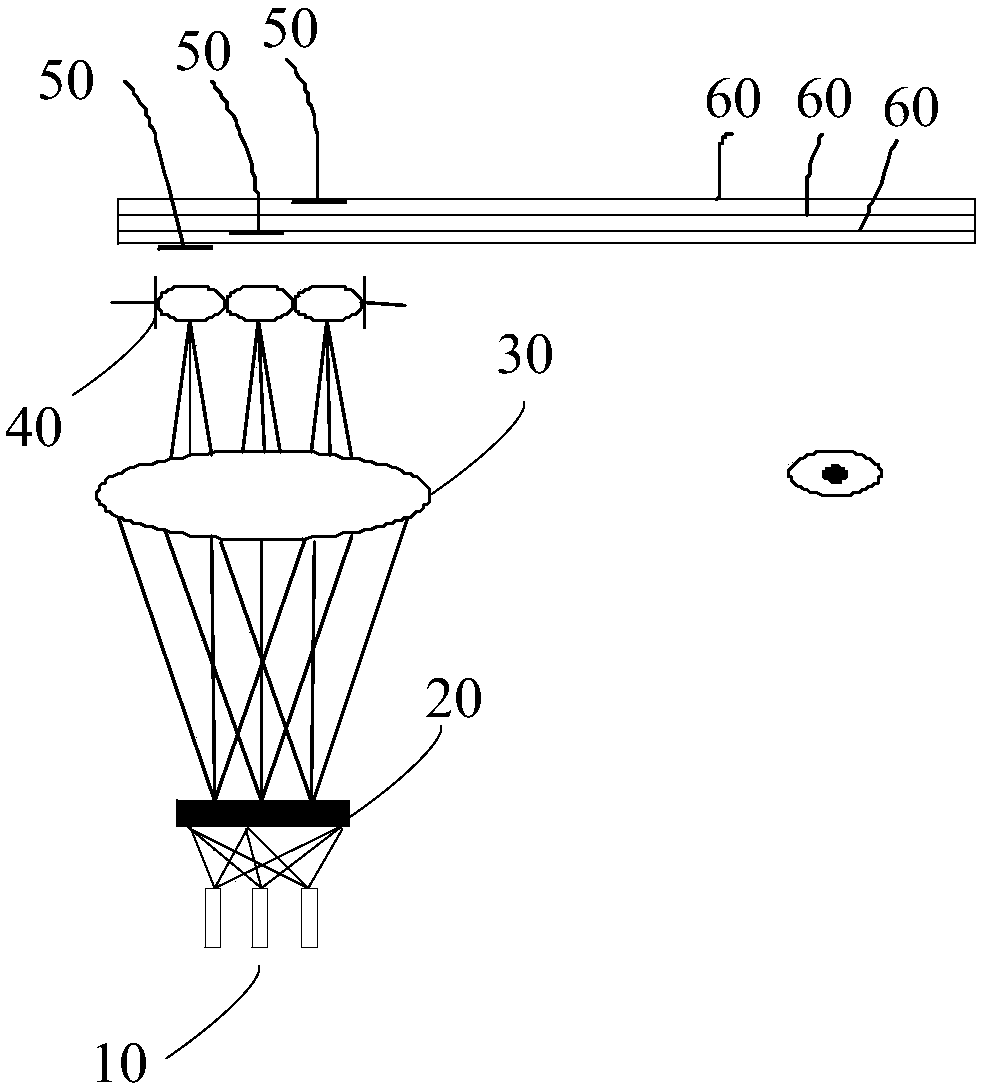
[0034] Please refer to figure 1 , figure 1 A schematic structural diagram of a near-eye display system provided by an embodiment of the present invention, the near-eye display system includes a light source 10, a display module 20, an eyepiece lens group 30, a lens array 40, a plurality of waveguide coupling devices 50, and a plurality of near-eye display panel waveguides 60 , the light source 10 includes a plurality of sub-light sou...


PUM


Abstract

The invention discloses a near-eye display system and a head-mounted display device. The near-eye display system comprises a light source, a display module, an ocular lens set, a lens array, a plurality of waveguide coupling devices and a plurality of near-eye display panel waveguides, wherein the light source comprises a plurality of sub-light sources, when an image to be projected is projected,light emitted by the current sub-light source is uniformly distributed on the display module; the display module is used for displaying an image to be projected, and the light beams corresponding to the image to be projected are emitted to the ocular lens set; the ocular lens set is used for emitting light corresponding to the image to be projected to a lens corresponding to the current sub-lightsource in the lens array; the lens is used for projecting the light beams corresponding to the image to be projected to the corresponding waveguide coupling device; the waveguide coupling devices areused for coupling the light beams corresponding to the image to be projected into the corresponding near-eye display panel waveguide; and the near-eye display panel waveguides are used for guiding thelight beams corresponding to the image to be projected into human eyes.

Description

technical field [0001] The present invention relates to the field of virtual reality and augmented reality, in particular to a near-eye display system and a head-mounted display device. Background technique [0002] Virtual reality (English: Virtual Reality; referred to as: VR) is a computer simulation system that can create and experience virtual worlds. The user is immersed in the environment, bringing the user a sensory experience beyond the real life environment. In terms of vision, virtual reality technology uses computer equipment to generate images of virtual scenes, and transmits image light to human eyes through optical devices, so that users can fully experience the virtual scene visually. [0003] Augmented reality (English: Augmented Reality; AR for short) is a technology that uses virtual objects or information to enhance the reality of real scenes. Augmented reality technology is usually based on real physical environment images obtained by image acquisition ...

Claims


Application Information

Patent Timeline
Patent Type & Authority Applications(China)
IPC IPC(8): G02B27/01
CPCG02B27/0172
Inventor 周旭东
Owner CHENGDU IDEALSEE TECH
Learn More