
Array substrate, manufacturing method, OLED device, manufacturing method thereof, and display device

A technology for array substrates and manufacturing methods, applied in semiconductor/solid-state device manufacturing, electrical solid-state devices, semiconductor devices, etc., can solve the problems of multiple inkjet times, uneven ink droplet size, and difficult control, etc. Less, to avoid the uneven size of ink droplet, reduce the effect of control difficulty

Active Publication Date: 2018-11-13
BOE TECH GRP CO LTD
View PDF4 Cites 28 Cited by
  • Summary
  • Abstract
  • Description
  • Claims
  • Application Information

AI Technical Summary

Problems solved by technology

[0005] In order to solve the problem that when the OLED pixel unit is produced by the existing inkjet printing method, each nozzle needs to perform more inkjet times. On the one hand, it is difficult to control, and on the other hand, there may be the problem of uneven ink droplet size caused by continuous inkjet printing. This paper The embodiment of the invention provides an array substrate and its manufacturing method, an OLED device and its manufacturing method, and a display device

Method used


Image

  • Array substrate, manufacturing method, OLED device, manufacturing method thereof, and display device
  • Array substrate, manufacturing method, OLED device, manufacturing method thereof, and display device
  • Array substrate, manufacturing method, OLED device, manufacturing method thereof, and display device

Examples


Embodiment Construction

[0054] In order to make the objectives, technical solutions and advantages of the present invention clearer, the embodiments of the present invention will be described in further detail below in conjunction with the accompanying drawings.

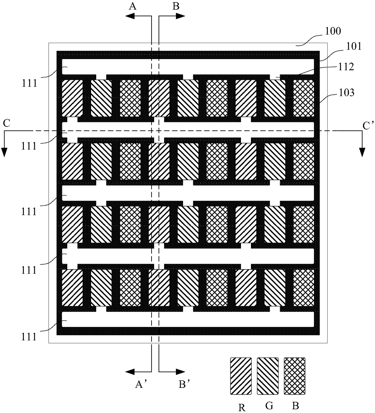
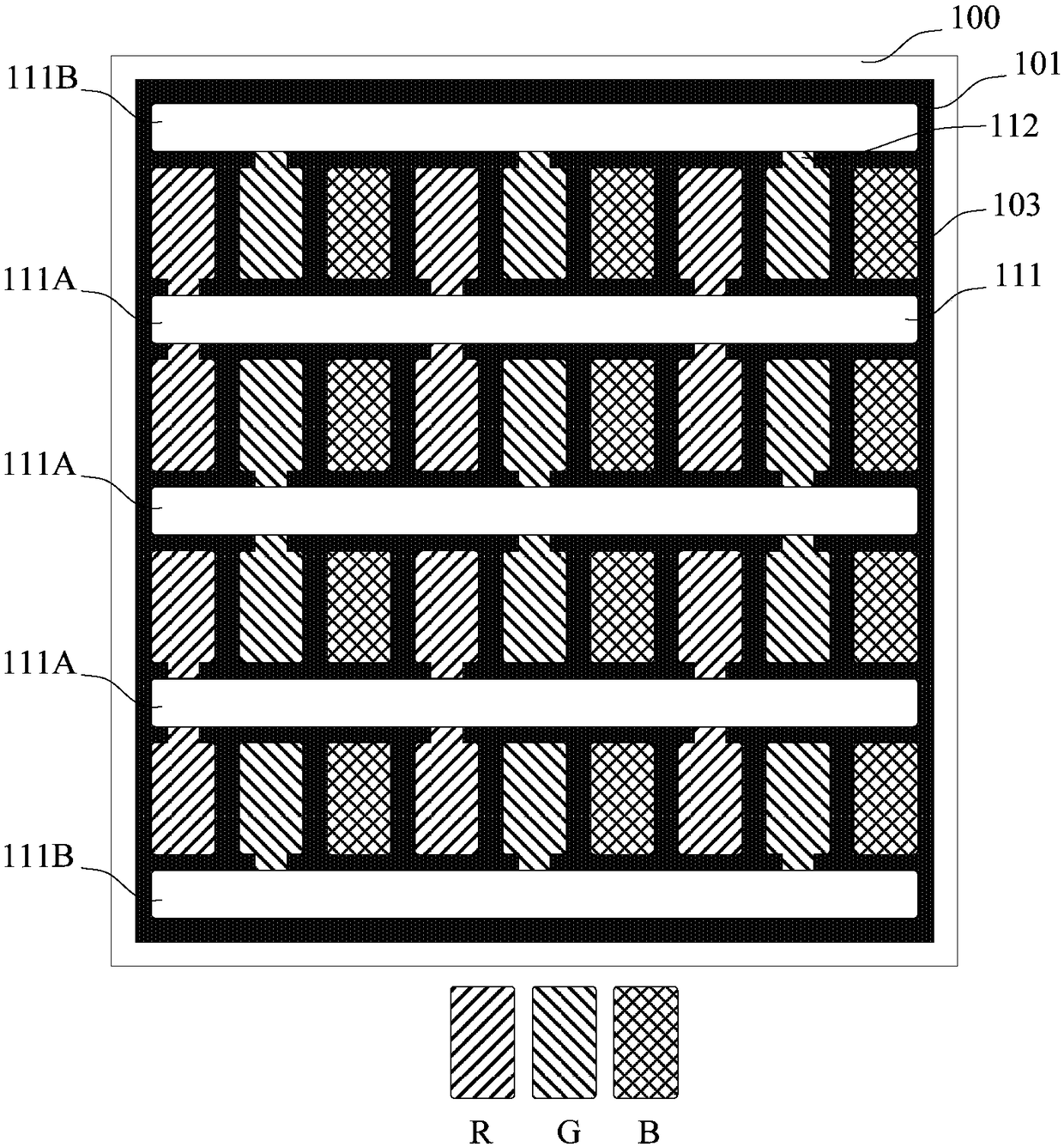
[0055] figure 1 with figure 2 Is a schematic diagram of the structure of an array substrate provided by an embodiment of the present invention, figure 1 Shown as figure 2 A cross-sectional view of the provided array substrate in the A-A' direction, figure 2 Shown as figure 1 The top view of the provided array substrate, see figure 1 with figure 2 The array substrate includes: a base substrate 100, a pixel defining layer 101 and an electrode 102 disposed on the base substrate 100, the pixel defining layer 101 divides the base substrate 100 into a plurality of sub-pixel regions 103, and the plurality of sub-pixel regions 103 are arranged In multiple rows, electrodes 102 are arranged in each sub-pixel area 103; the pixel defining layer 101 betw...


PUM


Abstract

The invention discloses an array substrate, a manufacturing method, an OLED device, a manufacturing method of an OLED device, and a display device and belongs to the display field. The array substrateincludes a substrate as well as a pixel defining layer and electrodes which are disposed on the substrate; the pixel defining layer divides the substrate into a plurality of sub-pixel regions; the plurality of sub-pixel regions are arranged in a plurality of rows; the electrodes are disposed in each of the sub-pixel regions; grooves located between adjacent two rows of sub-pixel regions are formed in the pixel defining layer; distances from the bottoms of the grooves to the substrate are greater than distances from the upper surfaces of the electrodes in the sub-pixel regions to the substrate; the grooves are communicated with at least two sub-pixel regions of the same color in the adjacent two rows of sub-pixel regions; and gaps located in each of the sub-pixel regions communicated withthe grooves are formed in the pixel defining layer, wherein the gaps are communicated with the grooves and the sub-pixel regions. Organic ink can be dropped into the grooves, so that OLED pixel unitscan be printed; and the number of the times of ink spray performed by a nozzle during printing is small.

Description

Technical field [0001] The invention relates to the field of displays, in particular to an array substrate and a manufacturing method, an OLED device and a manufacturing method thereof, and a display device. Background technique [0002] Currently, commonly used displays mainly include organic light-emitting displays (English Organic Light-Emitting Display, OLED for short) and liquid crystal displays (English Liquid Crystal Display, LCD for short). Among them, the OLED display panel mainly includes an array substrate and a cover plate. The array substrate is provided with OLED pixel units, and the cover plate covers the OLED pixel units on the array substrate. [0003] The OLED pixel unit includes an electrode, an organic thin film layer, and another electrode sequentially arranged on an array substrate. The organic thin film layer mainly includes a hole injection layer, a hole transport layer, an organic light emitting layer, and an electron transport layer stacked on the electrod...

Claims


Application Information

Patent Timeline
Patent Type & Authority Applications(China)
IPC IPC(8): H01L27/32H01L51/52H01L51/56
CPCH10K59/122H10K59/1201H10K71/611H10K59/131H10K59/35H10K59/173H10K59/179H10K50/13B41J3/407H10K59/353H10K71/00H10K50/11H10K50/15H10K50/17
Inventor 赵德江
Owner BOE TECH GRP CO LTD
Learn More