Novel high-speed magnetic levitation motor and method for detecting rotor position of motor

A high-speed motor and rotor position technology, applied in the direction of electromechanical devices, magnetic attraction or thrust holding devices, electrical components, etc., can solve the problems of impact, small installation size, etc., to prevent motor out of step, prevent irreversible demagnetization, Provides control over the effect of precision

Pending Publication Date: 2018-11-13
GREE ELECTRIC APPLIANCES INC
View PDF0 Cites 2 Cited by
  • Summary
  • Abstract
  • Description
  • Claims
  • Application Information

AI Technical Summary

Problems solved by technology

At present, the maximum speed of the resolver is within 30,000rpm, and the installation size of the resolver becomes smaller as the speed increases. For high-power high-speed motors, the large size of the motor affects its application in high-speed and high-power motors.

Method used


Image

  • Novel high-speed magnetic levitation motor and method for detecting rotor position of motor
  • Novel high-speed magnetic levitation motor and method for detecting rotor position of motor
  • Novel high-speed magnetic levitation motor and method for detecting rotor position of motor

Examples


Embodiment 1

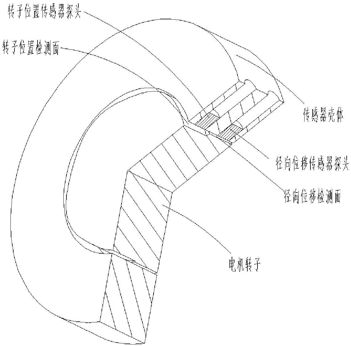
[0028] The invention provides a novel magnetic levitation high-speed motor, such as figure 1 As shown, it includes a rotor and a stator, and the rotor includes: a radial displacement detection cylinder and a position detection cylinder.

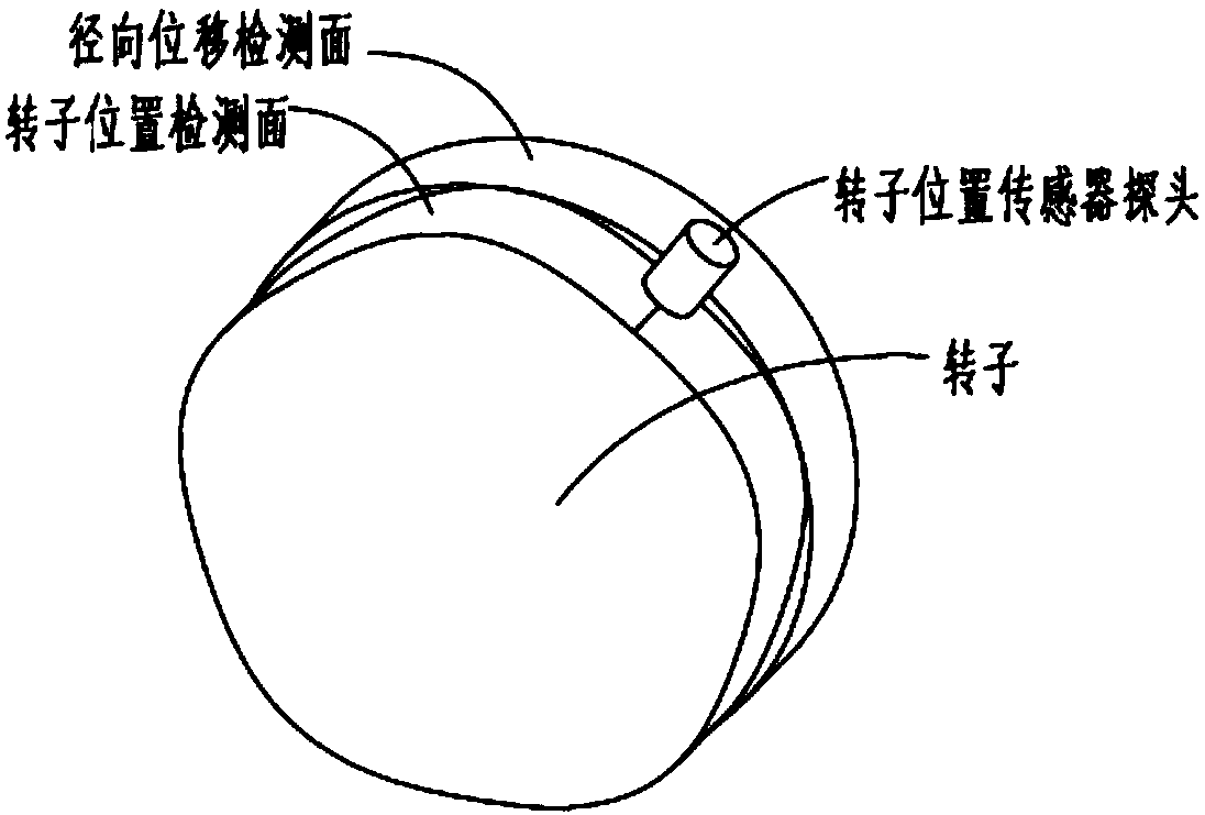
[0029] Wherein, the radial displacement detection cylinder and the position detection cylinder are coaxially arranged, and the radial displacement detection cylinder is a cylinder with a radius R, the position detection cylinder is a cylinder with regular arc-shaped edges, and the position detection cylinder The maximum radius of the body is R.

[0030] Optionally, the regular arc shape includes: at least one protrusion and at least one depression, where the protrusion and the depression appear sequentially at intervals.

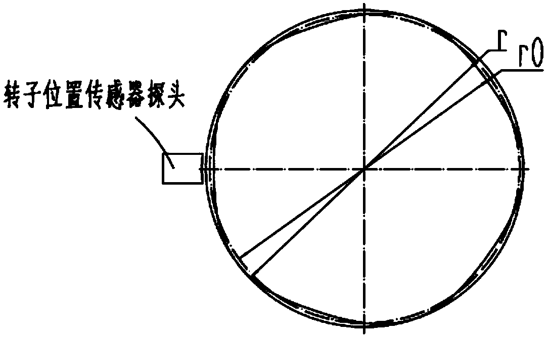
[0031] Optionally, the arc-shaped detection surface of the position detection cylinder of the motor rotor is designed according to the following formula. A cylindrical coordinate system is established with the axis of the ...

Embodiment 2

[0041] Based on the same inventive idea, the present invention provides a method for detecting the position of the motor rotor, which is used to detect the position of any of the above-mentioned new magnetic levitation high-speed motor rotors, including:

[0042] Detect the position of the radial displacement detection cylinder;

[0043] The position of the rotor is calculated from this position.

[0044] Wherein, the position of the radial displacement detection cylinder is the distance from the radial displacement sensor probe to the arc surface of the radial displacement detection cylinder. Such as Figure 4 Shown is a schematic diagram of the relationship between the detection distance change and the rotor position when the rotor rotates.

[0045] Optionally, calculating the position of the rotor includes: calculating the distance between the probe of the rotor position sensor and the arc surface of the position detection cylinder according to the following formula,

[...


PUM


Abstract

The invention relates to a novel high-speed magnetic levitation motor and a method for detecting a rotor position of the motor. The motor comprises a rotor and a stator, wherein the rotor comprises aradial displacement detection cylinder and a position detection cylinder; the radial displacement detection cylinder and the position detection cylinder are coaxially arranged; the radial displacementdetection cylinder is a cylinder of which the radius is R; the position detection cylinder is a cylinder of which the edge is in a regular arc form; and the maximum radius of the position detection cylinder is R. According to the novel high-speed magnetic levitation motor, the rotor is designed into the structure of which the upper part and the lower part are different in shape, and the distancesbetween the outer surfaces of the upper part and the lower part and a detection sensor are detected through the detection sensor to obtain a space position of the rotor, thereby achieving indirect measurement of a space angle of the rotor.

Description

technical field [0001] The invention belongs to the field of motors, and in particular relates to a novel magnetic levitation high-speed motor and a method for detecting the rotor position of the motor. Background technique [0002] The rotor of a high-speed permanent magnet motor can reach tens of thousands or even hundreds of thousands of revolutions per minute. Conventional high-speed motor control uses a rotorless position control algorithm for motor control. Due to inaccurate position estimation, the motor will lose its step, and in severe cases, it may cause the rotor magnet to break. Irreversible demagnetization. [0003] The resolver is often used to provide the real-time position of the rotor in the occasions with high requirements on the motor speed. At present, the maximum speed of the resolver is within 30,000rpm, and the installation size of the resolver becomes smaller as the speed increases. For high-power high-speed motors, the large size of the motor affect...

Claims


Application Information

Patent Timeline
Patent Type & Authority Applications(China)
IPC IPC(8): H02N15/00H02K11/21
CPCH02N15/00H02K11/21
Inventor 李广海陈彬张小波刘健宁张芳贾金信郭长光魏琼李忠雨闫瑾彭利民熊博文梁建东王泽业
Owner GREE ELECTRIC APPLIANCES INC
Why Eureka
Try Eureka