
Primary side coil current measurement circuit of magnetic-induced radio energy transmission system

A technology of wireless energy transmission and current measurement circuit, which is applied in the direction of measuring electrical variables, measuring current/voltage, measuring devices, etc., can solve the problems of increasing cost and the difficulty of directly measuring coil current, so as to ensure reliability and simple structure Effect

Pending Publication Date: 2019-10-01
上海万暨电子科技有限公司
View PDF0 Cites 0 Cited by
  • Summary
  • Abstract
  • Description
  • Claims
  • Application Information

AI Technical Summary

Problems solved by technology

[0002] Electric vehicles need to be charged frequently or every day. When wireless charging is used for electric vehicles, the coil of the wireless power transfer (WPT) system is placed on the ground side, and the measurement circuit is in the control cabinet on the ground side. The distance between the two is about 5-7m. The method of directly measuring the coil current is difficult and needs to increase the cost, and the WPT system needs to monitor the current of the primary coil in real time to judge the operating status of the system, so a circuit is needed to realize the indirect measurement of the current of the primary coil

Method used


Image

  • Primary side coil current measurement circuit of magnetic-induced radio energy transmission system
  • Primary side coil current measurement circuit of magnetic-induced radio energy transmission system
  • Primary side coil current measurement circuit of magnetic-induced radio energy transmission system

Examples


Embodiment Construction

[0028] In order to facilitate those skilled in the art to better understand the present invention, the present invention will be described in further detail below in conjunction with the accompanying drawings and specific embodiments. The following is only exemplary and does not limit the protection scope of the present invention.

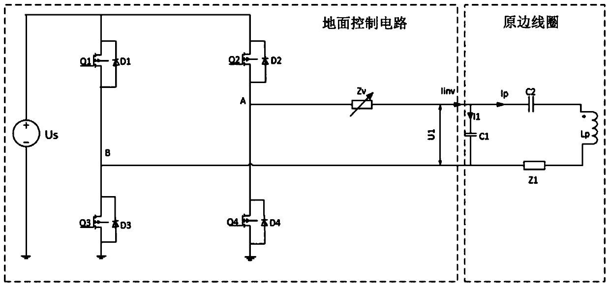
[0029] Such as figure 1 As shown, the current measurement circuit of a primary coil of a magnetic induction wireless power transmission system described in this embodiment includes a ground control circuit and a primary coil arranged on the ground. Wherein, the primary coil is arranged in an appropriate parking area of ​​the electric vehicle parking space, and when the electric vehicle is parked, the installation position of the vehicle-mounted coil (i.e. the secondary coil) should correspond to the primary coil as much as possible; the ground control circuit is placed in a control In the cabinet, the control cabinet is generally fixed on the wall ...


PUM


Abstract

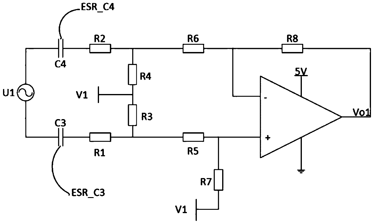
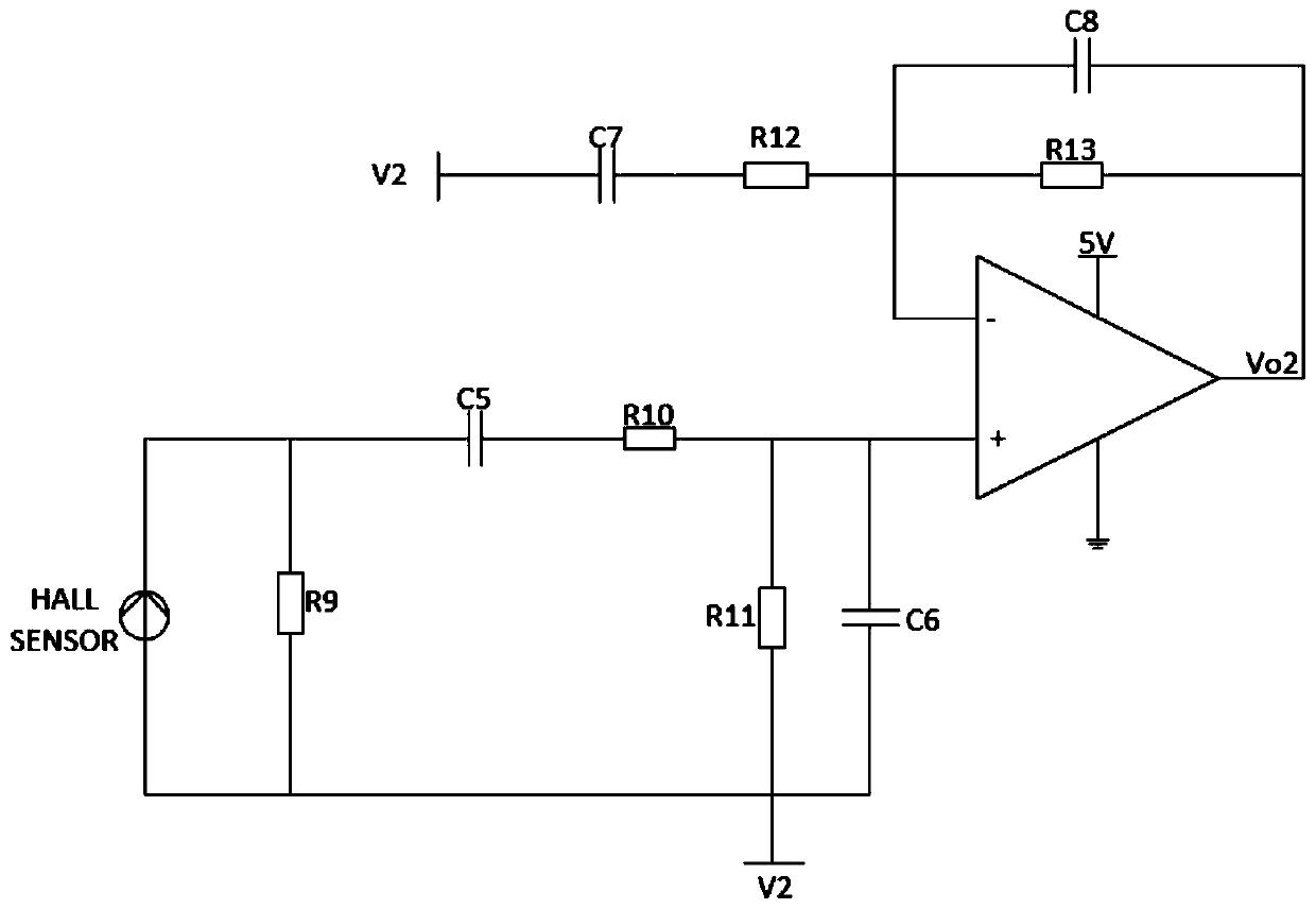
The invention discloses a primary side coil current measurement circuit of a magnetic-induced radio energy transmission system. The magnetic-induced radio energy transmission system comprises a groundcontrol circuit and a primary side coil arranged on the ground; the primary side coil current measurement circuit comprises an output voltage sampling circuit for processing output voltage of a ground control circuit and outputting the processed output voltage of the ground control circuit; and an output current sampling circuit for processing the output current of an inverter and outputting thevoltage corresponding to the processed output current of the inverter. The primary side coil current measurement circuit can realize indirect measurement on the primary side coil current, and then a system running state is judged by monitoring the primary side coil current in real time, and the reliability of the system running is guaranteed; and the primary side coil current measurement circuit is simple in structure, low in cost and capable of realizing remote measurement.

Description

technical field [0001] The invention relates to the technical field of wireless power transmission, in particular to a primary coil current measurement circuit of a magnetic induction wireless power transmission system. Background technique [0002] Electric vehicles need to be charged frequently or every day. When wireless charging is used for electric vehicles, the coil of the wireless power transfer (WPT) system is placed on the ground side, and the measurement circuit is in the control cabinet on the ground side. The distance between the two is about 5-7m. The method of directly measuring the coil current is difficult and needs to increase the cost, and the WPT system needs to monitor the current of the primary coil in real time to judge the operating status of the system, so a circuit is needed to realize the indirect measurement of the current of the primary coil. Contents of the invention [0003] In order to overcome the deficiencies of the above technologies, the ...

Claims


Application Information

Patent Timeline
Patent Type & Authority Applications(China)
IPC IPC(8): G01R19/00
CPCG01R19/00
Inventor 杨国勋刘洪亮寇秋林
Owner 上海万暨电子科技有限公司
Learn More