Control parameter input method for illumination system, and operation terminal
A technology for controlling parameters and lighting systems, applied to TV system components, data processing input/output processes, lighting devices, etc., can solve the problem of inability to determine dimming control lighting fixtures, unable to input lighting fixture dimming control parameters, etc. question
- Summary
- Abstract
- Description
- Claims
- Application Information
AI Technical Summary
Problems solved by technology
Method used
Image

Examples
Embodiment approach 1
[0031] [1-1. Outline structure of lighting system]
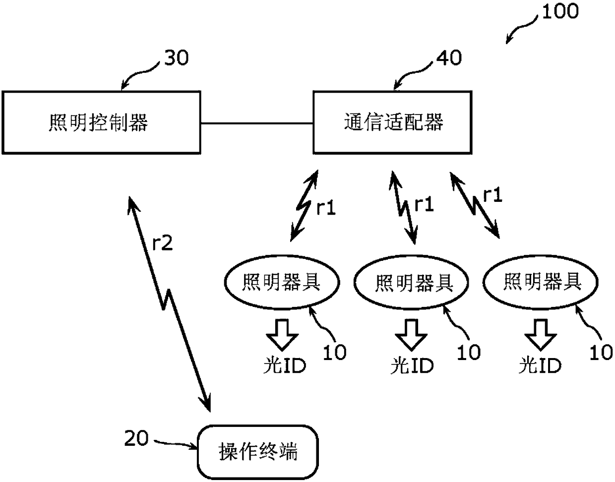
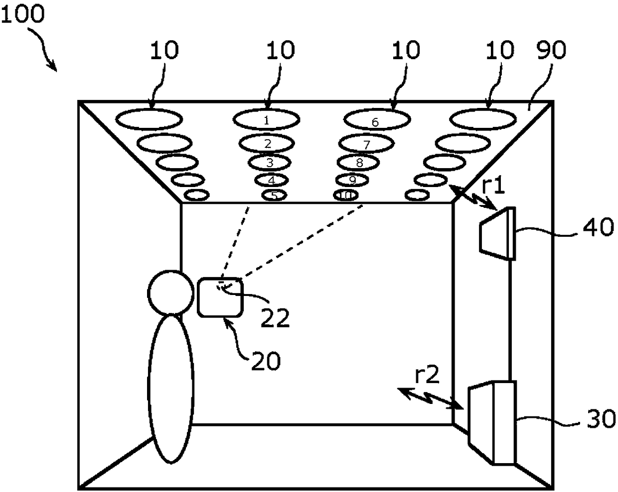
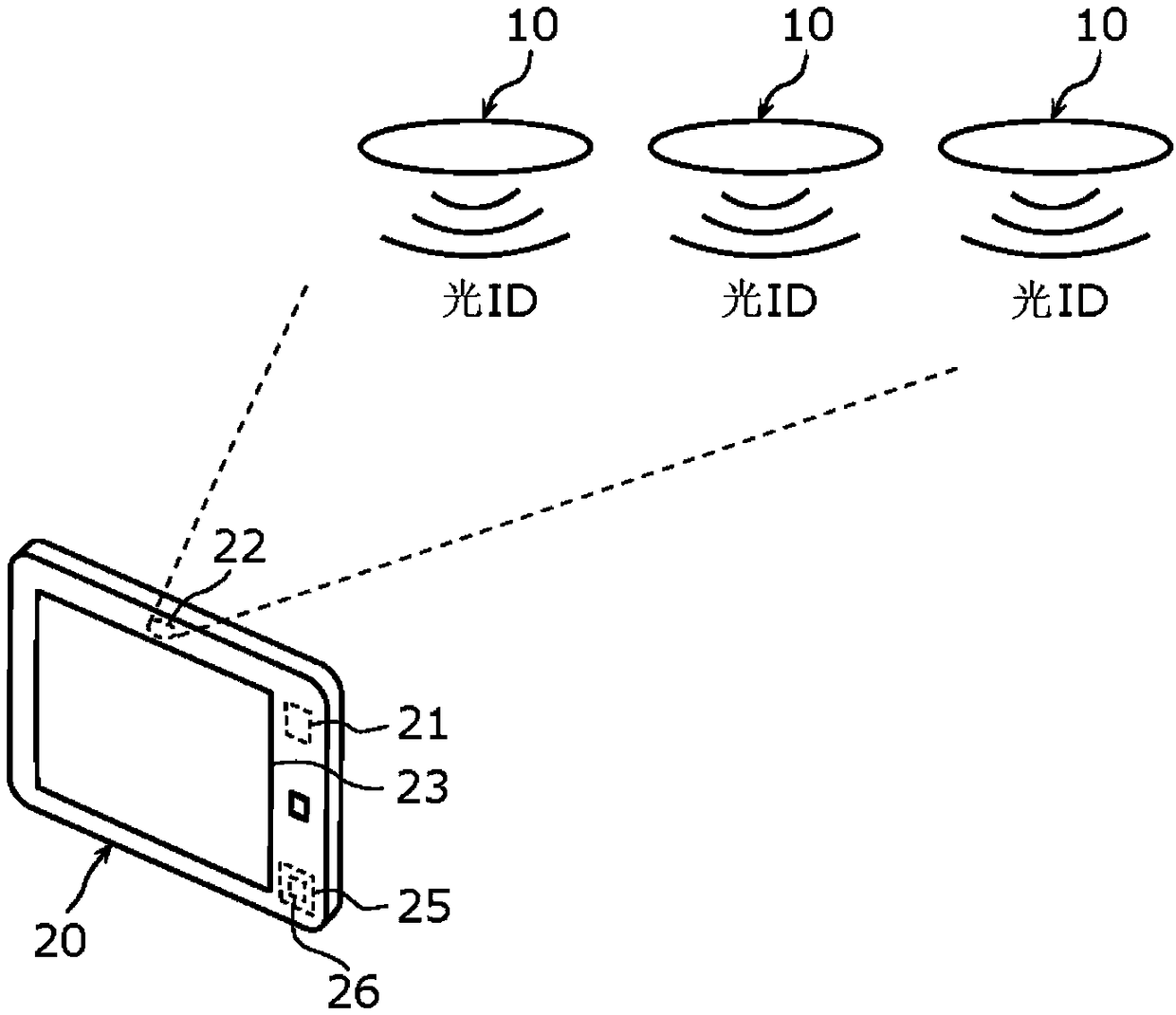
[0032] figure 1 It is a schematic diagram showing the lighting system 100 according to Embodiment 1, that is, the lighting fixture 10 , the lighting controller 30 , the communication adapter 40 , and the operation terminal 20 included in the lighting system 100 . figure 2 It is a figure which shows an example of the arrangement|positioning of the lighting fixture 10, the lighting controller 30, the communication adapter 40, and the operation terminal 20. image 3 It is a figure which shows the state which photographed the lighting fixture 10 using the operation terminal 20.
[0033] The lighting system 100 includes a plurality of lighting fixtures 10 , a lighting controller 30 , a communication adapter 40 connected to the lighting controller 30 , and an operation terminal 20 . exist figure 1 In the figure, three lighting fixtures 10 are shown, but this figure is an example, and in fact there are sometimes ceilings 90 o...
Embodiment approach 2
[0094] Embodiment 2 is a form of grouping a plurality of lighting fixtures 10 . Figure 10 It is a figure which shows an example of the image displayed on the operation terminal 20 in Embodiment 2. Figure 11 is expressed in order in Figure 10 The shown image is a diagram of an image displayed on the operation terminal 20 thereafter.
[0095] First, steps S11 to S15 are executed in the same manner as in the first embodiment. Then, in step S15 , selection candidates for control parameters are displayed on the parameter selection unit 23 b of the touch panel 23 . For example, if Figure 10 As shown in , selection candidates for control parameters such as "group", "brightness, light color", and "communication adapter" are displayed. In Embodiment 2, "group" is selected as the control parameter to be adjusted later.
[0096] Next, a predetermined lighting fixture 10 is selected from the images displayed on the touch panel 23 (S16). Specifically, as Figure 11 As shown in (...
Embodiment approach 3
[0103] Embodiment 3 is a mode in which the input of the control parameters of the lighting fixture 10 is performed based on a still image. Figure 12 It is a figure which shows the image displayed on the operation terminal 20 in Embodiment 3 in order.
[0104] First, if Figure 12As shown in (a), the camera 22 of the operation terminal 20 captures a plurality of lighting fixtures 10 ( S11 ), and displays an image including the lighting fixtures 10 captured by the camera 22 on the touch panel 23 ( S12 ). And steps S13-S15 are performed similarly to Embodiment 1.
[0105] Afterwards, in Embodiment 3, as in Figure 12 As shown in (b), an image saving step of saving the image captured by the camera 22 as a still image is executed. Specifically, an image including the captured lighting fixture 10 and information associated with identification information corresponding to the lighting fixture 10 (for example, numbers “1 to 10”) are stored as still images and displayed on the touc...
PUM
 Abstract
Description
Claims
Application Information
 - R&D
- Intellectual Property
- Life Sciences
- Materials
- Tech Scout
- Unparalleled Data Quality
- Higher Quality Content
- 60% Fewer Hallucinations
Browse by: Latest US Patents, China's latest patents, Technical Efficacy Thesaurus, Application Domain, Technology Topic, Popular Technical Reports.
© 2025 PatSnap. All rights reserved.Legal|Privacy policy|Modern Slavery Act Transparency Statement|Sitemap|About US| Contact US: help@patsnap.com