A self-hydrating flowerpot

An automatic water replenishment and flowerpot technology, which is applied in automatic watering devices, horticulture, agriculture, etc., can solve problems such as dry green plants, and achieve the effect of constant nutrient solution concentration, constant water level, and normal growth.

Active Publication Date: 2020-11-10
NANJING QIJUE ELECTRONICS TECH CO LTD
View PDF5 Cites 0 Cited by
  • Summary
  • Abstract
  • Description
  • Claims
  • Application Information

AI Technical Summary

Problems solved by technology

[0003] The purpose of the present invention is to solve the problem that the existing flowerpots in the process of planting green plants can easily cause the green plants to dry up due to the inability to replenish water in time, and propose an automatic water replenishing flowerpot, which can realize automatic watering and ensure The water in the sump is always kept at the same level to ensure the normal growth of green plants

Method used


Image

  • A self-hydrating flowerpot
  • A self-hydrating flowerpot

Examples


Embodiment 1

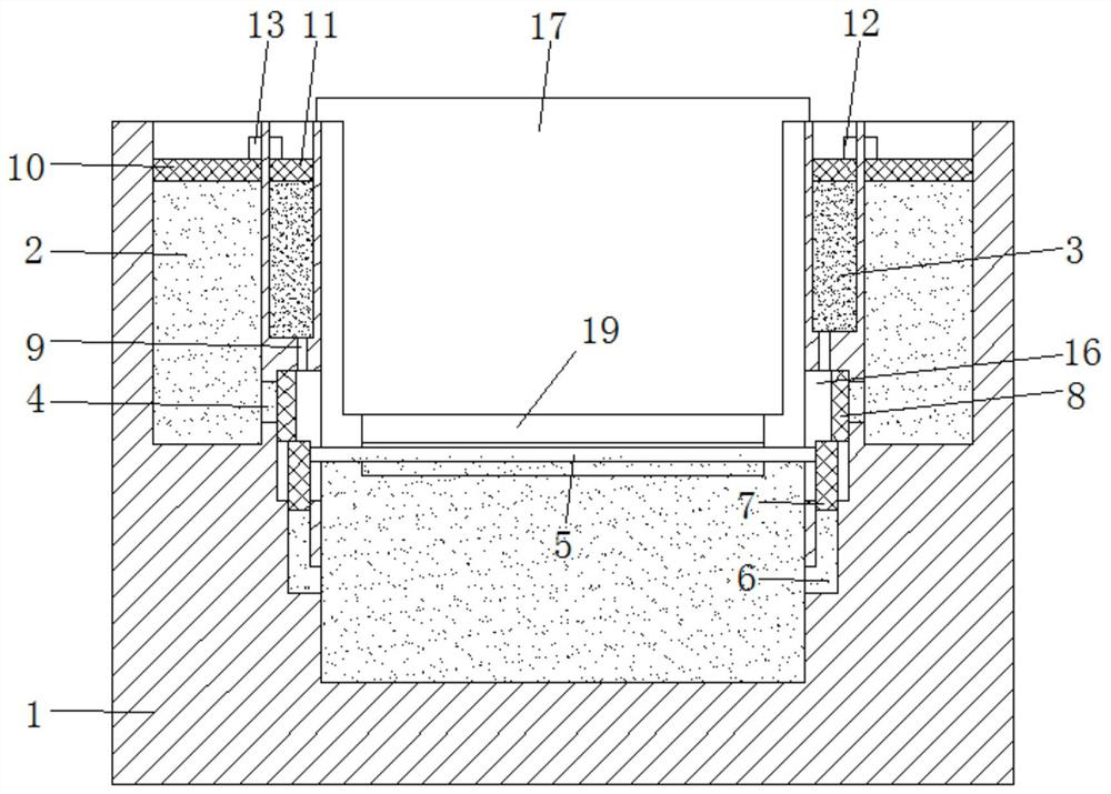
[0015] refer to figure 1 , a kind of automatic replenishing water flower pot, comprises catchment basin 1, the planting pot 17 that is arranged on the inside of catchment basin, and the sponge block 19 that is arranged on the bottom of planting pot, and the upper end surface of catchment basin 1 is provided with annular water storage tank 2 and The annular liquid storage tank 3, the left and right inner cavity walls of the water collection basin 1 are vertically provided with chutes 16, and the two chute 16 and the annular water storage tank 2 are provided with water holes 4, and the two chute 16 There are capillary holes 9 running through the ring-shaped liquid storage tank 3. Because the pore diameter of the capillary holes 9 is small, it can reach the level of liquid seal, so the nutrient solution in the annular liquid storage tank 3 cannot flow out under its own gravity. The bottom side wall of chute 16 is all provided with the L-shaped passage 6 that is communicated with ...

Embodiment 2

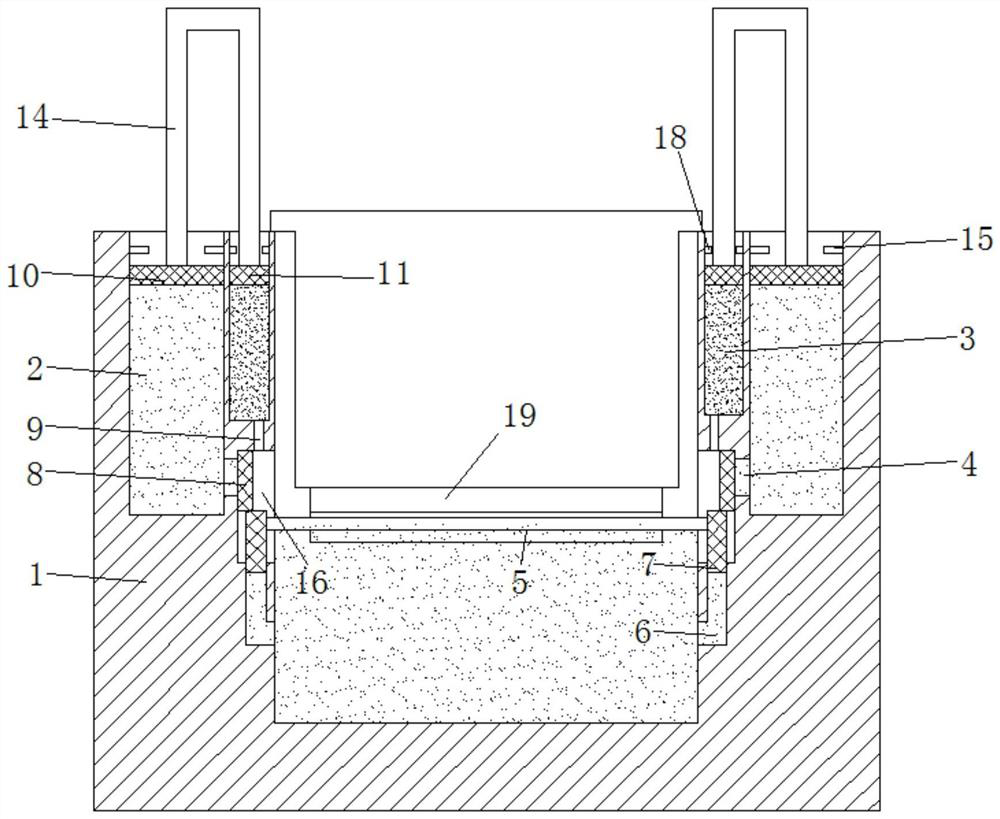
[0019] refer to figure 2 , The difference between this embodiment and Embodiment 1 is that the connection mechanism includes an inverted U-shaped rod 14, and the two ends of the inverted U-shaped rod 14 are respectively connected to the upper end side wall of the first annular piston 10 and the upper end of the second annular piston 11. The side walls are fixedly connected, and the inner wall of the annular water storage tank 2 is provided with a first limiting block 18 , and the inner wall of the annular liquid storage tank 3 is provided with a second limiting block 15 .

[0020] Compared with Embodiment 1, the advantage of this embodiment is that the first magnet 13 and the second magnet 12 are replaced by inverted U-shaped rods 14, and the inner sidewalls of the annular water storage tank 2 and the annular liquid storage tank 3 are respectively provided with a plurality of first magnets. Two limit blocks 15 and a plurality of first limit blocks 18, when the first annular p...


PUM


Abstract

The invention discloses an automatic water replenishing flowerpot. The automatic water replenishing flowerpot comprises a water collecting basin, a planting basin arranged on the inner side of the water collecting bin, and a sponge block arranged at the bottom of the planting basin. An annular water storage groove and an annular liquid storage groove are formed in the upper end face of the water collecting basin. Sliding grooves are vertically formed in the left inner cavity wall and the right inner cavity wall of the water collecting basin, water flow holes penetrate through the portions between the two sliding grooves and the annular water storage groove, capillary holes penetrate through the portions between the two sliding grooves and the annular liquid storage groove, L-shaped channels communicated with the inner cavity walls of the water collecting basin are formed in the bottom side walls of the two sliding grooves, floating blocks are arranged in the vertical portions of the L-shaped channels, a floating rod is connected between the upper ends of the two floating blocks, and the side walls of the upper ends of the two floating blocks are fixedly connected with check blocksfor blocking the water flow holes. The structural design is reasonable, automatic water adding can be achieved, it is guaranteed that water in the water collecting basin is always kept in the same horizontal plane, and therefore normal growth of green plants is guaranteed.

Description

technical field [0001] The invention relates to the technical field of green planting, in particular to an automatic water replenishing flowerpot. Background technique [0002] At present, potted green plants are very common in the office. The planter of potted green plants is generally composed of a water collection basin, a planting pot arranged inside the water collection basin, and a sponge block arranged at the bottom of the planting pot. The soil and the green plant body, and then connect the planting pot to the water collection basin, so that the water in the water collection basin can provide moisture to the cultivation soil and the green plant body, but often due to long-term placement, people forget to add water to the water collection basin. Continuous watering in the pot, when the sponge block at the bottom of the planting pot is higher than the water surface, the planting pot cannot absorb water, and when the water collection basin is filled with water, because ...

Claims


Application Information

Patent Timeline
Patent Type & Authority Patents(China)
IPC IPC(8): A01G9/02A01G27/06A01C23/00
CPCA01G9/02A01G27/06
Inventor 陈龙
Owner NANJING QIJUE ELECTRONICS TECH CO LTD
Why Eureka
Try Eureka