Robot with cleaning function

A robot and functional technology, applied in the field of robots, can solve the problems of high labor intensity of cleaning personnel and high risk of high-altitude operations, and achieve the effect of reducing cleaning costs, reducing labor intensity, and improving work efficiency

Pending Publication Date: 2018-11-16
柏秋
View PDF0 Cites 3 Cited by
  • Summary
  • Abstract
  • Description
  • Claims
  • Application Information

AI Technical Summary

Problems solved by technology

[0002] With the rapid development of the economy, high-rise buildings are installed in various public areas. In high-rise buildings, most of them use glass curtain walls. In order to maintain the cleanliness and tidiness of the glass curtain walls, the glass curtain walls need to be cleaned regularly. In the prior art , Usually the glass curtain wall is cleaned manually. For the glass curtain wall at a higher position, the cleaning personnel are often suspended by ropes to clean the glass curtain wall. The high-altitude operation is dangerous and the labor intensity of the cleaning personnel is relatively high. Big

Method used


Image

  • Robot with cleaning function
  • Robot with cleaning function
  • Robot with cleaning function

Examples


Embodiment 1

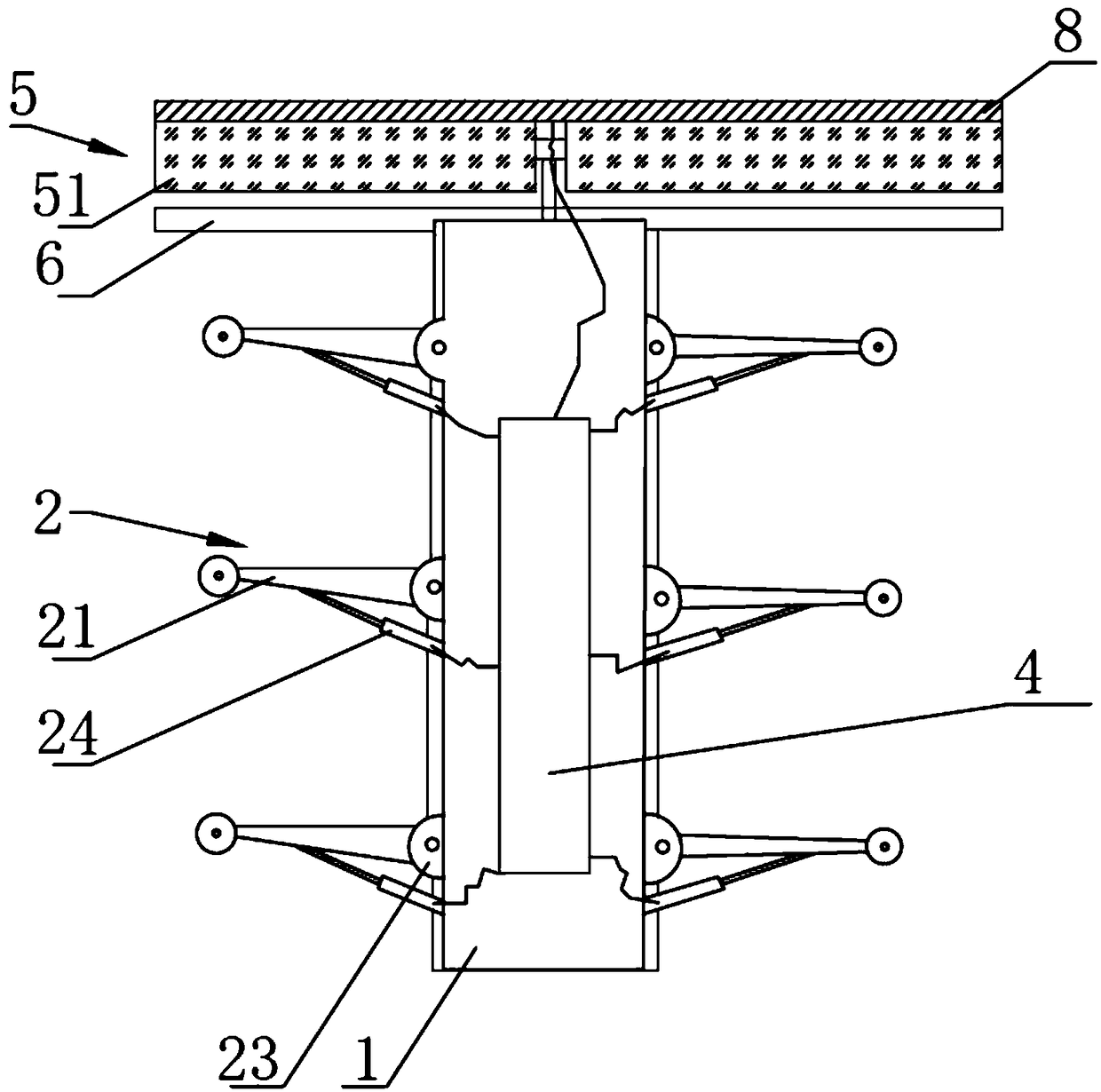
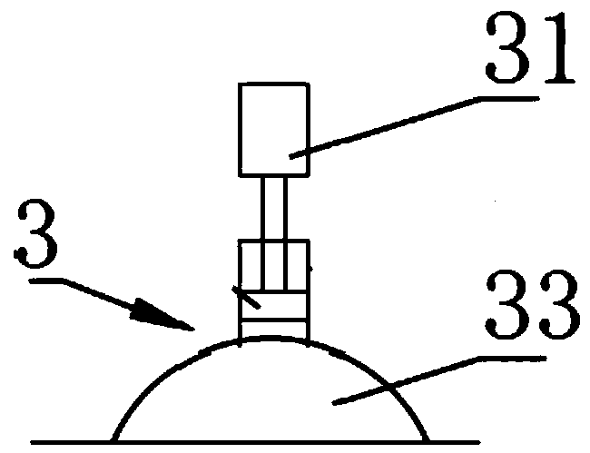
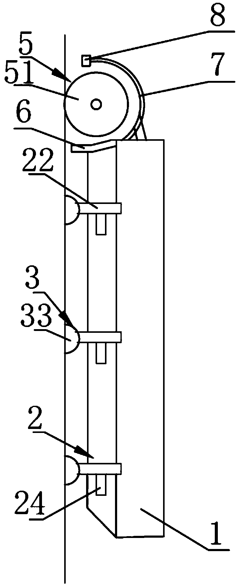
[0035]The present invention provides a robot with a cleaning function, which includes: a frame 1, a plurality of pairs of mechanical legs 2, a plurality of fastening devices 3, a controller 4 and a cleaning device 5, and the plurality of pairs of mechanical legs 2 are respectively related to the The frame 1 is arranged symmetrically, and one end of a plurality of pairs of mechanical legs 2 is symmetrically arranged on both sides of the frame 1 with respect to the frame 1, and the cleaning device 5 is arranged at one end of the frame 1 A plurality of fastening devices 3 are arranged on the other ends of the plurality of mechanical legs 2 respectively, the fastening devices 3 are fastened to the surface of the object to be cleaned, and the controller 4 is arranged on the frame 1 Above, the controller 4 is connected with the cleaning device 5 and controls the opening and closing of the cleaning device, and the controller 4 is connected with the mechanical leg 2 and controls the mo...

Embodiment 2

[0040] On the basis of Embodiment 1, the mechanical leg 2 of this embodiment includes: a first connecting rod 21, a second connecting rod 22, a third connecting rod 23, a first pushing device 24 and a second pushing device 25, so One end of the third connecting rod 23 is rotatably arranged on the side wall of the frame 1, and the base of the first pushing device 24 is arranged on the upper rear side of one end of the third connecting rod 23. One end of a connecting rod 21 is rotatably connected with the third connecting rod 23, and the base of the first pushing device 24 is rotatably arranged on the side wall of the frame 1, and the base of the first pushing device 24 The output end is rotatably connected to the middle part of the first connecting rod 21, the other end of the first connecting rod 21 is rotatably connected to one end of the second connecting rod 22, and the base of the second pushing device 25 can be Rotately arranged on the first connecting rod 221, the output...

Embodiment 3

[0043] On the basis of Embodiment 2, the first pushing device 24 and the second pushing device 25 of this embodiment are oil cylinders, air cylinders or air compression pumps of the same type.

[0044] Wherein, the model of the electric oil cylinder can be: mob.

[0045] Both the first pushing device and the second pushing device are electric oil cylinders, so that the first pushing device and the second pushing device can be uniformly controlled by the controller, so as to realize different motion states.


PUM


Abstract

The invention provides a robot with a cleaning function, which comprises a frame, a plurality of pairs of mechanical legs, a plurality of fastening devices, a controller and a cleaning device, whereinone end of the plurality of pairs of the mechanical legs is symmetrically arranged on two sides of the frame respectively with respect to the frame, The cleaning device is arranged at one end of theframe, the controller is arranged on the frame, the controller is connected with the cleaning device, the fastening device is arranged at the other end of the mechanical legs, and the fastening deviceis buckled with the surface of an object to be cleaned. Through the special combination of the fastening device and the mechanical legs, the robot can adsorb and walk on the end surface of a glass curtain wall, by arranging the cleaning device, the robot can clean the glass curtain wall, the labor intensity of a user is reduced and the working efficiency is improved, the cleaning cost of the glass curtain wall is reduced.

Description

technical field [0001] The invention relates to a robot, in particular to a robot with a cleaning function. Background technique [0002] With the rapid development of the economy, high-rise buildings are installed in various public areas. In high-rise buildings, most of them use glass curtain walls. In order to maintain the cleanliness and tidiness of the glass curtain walls, the glass curtain walls need to be cleaned regularly. In the prior art , Usually the glass curtain wall is cleaned manually. For the glass curtain wall at a higher position, the cleaning personnel are often suspended by ropes to clean the glass curtain wall. The high-altitude operation is dangerous and the labor intensity of the cleaning personnel is relatively high. Big. Contents of the invention [0003] The technical problem to be solved by the present invention is to provide a robot with a cleaning function in view of the deficiencies in the prior art. [0004] The technical solution of the pre...

Claims


Application Information

Patent Timeline
Patent Type & Authority Applications(China)
IPC IPC(8): A47L1/02A47L11/38A47L11/40
CPCA47L1/02A47L11/38A47L11/40A47L11/4066A47L11/4088A47L11/4094A47L2201/00E04G23/002
Inventor 柏秋柏晓臣
Owner 柏秋
Why Eureka
Try Eureka