Numerical control bending machine transmission system and numerical control bending machine

A technology of transmission system and bending machine, applied in the field of bending machine, can solve the problems of poor processing accuracy and accuracy consistency, aging oil leakage of hydraulic system parts, deflection affecting the accuracy of processed parts, etc., to achieve the improvement of processing accuracy and consistency of precision Sex, the effect of overcoming deflection

Active Publication Date: 2018-11-16
王勇
View PDF4 Cites 3 Cited by
  • Summary
  • Abstract
  • Description
  • Claims
  • Application Information

AI Technical Summary

Problems solved by technology

This kind of traditional bending machine is affected by the form of its driving mechanism and the hydraulic system itself, the processing accuracy and accuracy consistency of the equipment are relatively poor, and the phenomenon of aging and oil leakage of hydraulic system parts often occurs
In addition, because the driving cylinder is located at the shoulders on both sides of the upper slider, it is impossible to realize the uniform distribution of the bending driving force in the entire range of the workbench. Bending processing, especially when bending long-sized medium-thick plate parts, will cause large The deflection affects the accuracy of the machined parts

Method used


Image

  • Numerical control bending machine transmission system and numerical control bending machine
  • Numerical control bending machine transmission system and numerical control bending machine
  • Numerical control bending machine transmission system and numerical control bending machine

Examples


Embodiment 1

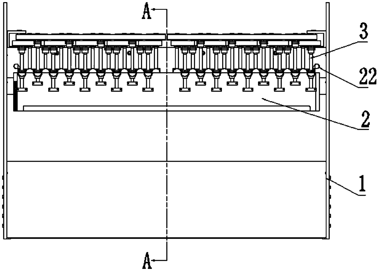
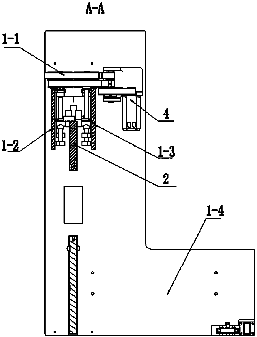
[0033] Such as Figure 1 to Figure 3 As shown, a CNC bending machine transmission system includes a slider body 2 and a ball screw drive mechanism 3. The slider body 2 is evenly distributed with force-bearing parts, and the ball screw drive mechanism 3 is provided with multiple One, the ball screw drive mechanism 3 exerts a downward force on the slider body 2 through the force-bearing member on the slider body 2 .

[0034] In the present invention, a plurality of force-bearing parts are arranged on the slider body, and the ball screw drive mechanism directly exerts force on the force-bearing parts, and then applies force to the slider body through the force-bearing parts, because the force-bearing parts are evenly distributed on the slider body Therefore, the force distribution on the entire slider body is relatively uniform, and the slider body moves downward to realize the bending process of the parts, and the bending force exerted by the slider body on the parts is evenly d...

Embodiment 2

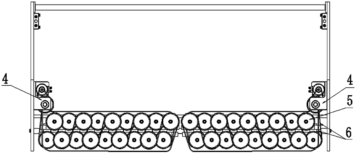
[0050] Such as Figure 6 to Figure 8 As shown, a CNC bending machine transmission system includes a slider body 2 and a ball screw drive mechanism 3. The slider body 2 is evenly distributed with force-bearing parts, and the ball screw drive mechanism 3 is provided with multiple One, the ball screw drive mechanism 3 exerts a downward force on the slider body 2 through the force-bearing member on the slider body 2 .

[0051] In the present invention, a plurality of force-bearing parts are arranged on the slider body 2, and the ball screw drive mechanism 3 directly exerts force on the force-bearing parts, and then applies force to the slider body 2 through the force-bearing parts. Since the force-bearing parts are evenly distributed on the The slider body 2, so the force distribution on the entire slider body 2 is relatively uniform, the slider body 2 moves downward to realize the bending process of the part, and the bending force exerted by the slider body 2 on the part is evenl...


PUM


Abstract

The invention discloses a numerical control bending machine transmission system and a numerical control bending machine. The numerical control bending machine transmission system comprises a sliding block body and a ball screw driving mechanism, wherein stress parts are uniformly distributed on the sliding block body, the plurality of ball screw driving mechanisms are arranged, and the ball screwdriving mechanism is used for applying downward acting force on the sliding block body through the stress pieces on the sliding block body. According to the numerical control bending machine transmission system and the numerical control bending machine, the sliding block body is provided with the plurality of stress pieces, the ball screw driving mechanism directly applies force to the stress pieces, the stress pieces applies force to the sliding block body, due to the fact that the stress pieces are uniformly distributed on the sliding block body, the stress distribution on the whole slidingblock body is more uniform, the sliding block body moves downwards so as to realize bending machining of parts, moreover, the bending force applied to the parts by the sliding block body is uniformlydistributed in the range of a whole working table, so that the relatively large deflection generated during bending machining especially bending machining of long-size medium-thickness plate parts isovercome, and the machining precision and the consistency of the precision can be improved.

Description

technical field [0001] The invention relates to a transmission system of a numerically controlled bending machine and a numerically controlled bending machine, belonging to the technical field of bending machines. Background technique [0002] Existing bending machines / press brakes usually use two or more hydraulic cylinders to drive the upper slider of the bending machine and then drive the upper mold to slide up and down so as to realize the bending process of the parts. This kind of traditional bending machine is affected by the form of its driving mechanism and the hydraulic system itself. The processing accuracy and accuracy consistency of the equipment are relatively poor, and the aging and oil leakage of hydraulic system parts also often occurs. In addition, because the driving cylinder is located at the shoulders on both sides of the upper slider, it is impossible to realize the uniform distribution of the bending driving force in the entire range of the workbench. B...

Claims


Application Information

Patent Timeline
Patent Type & Authority Applications(China)
IPC IPC(8): B21D5/01F16H47/00
CPCB21D5/01F16H47/00
Inventor 王勇林艳
Owner 王勇
Why Eureka
Try Eureka