Pipe section punching machine, pipe section feeding device and pipe section processing equipment

A punching device and punching machine technology, applied in metal processing equipment, feeding device, positioning device and other directions, can solve the problems of high cost, complicated structure of feeding device, complicated high-precision control method, etc., and achieve reasonable structure, The effect of improving production efficiency and compact overall structure

Pending Publication Date: 2018-11-16
浙江长兴和良智能装备有限公司
View PDF2 Cites 9 Cited by
  • Summary
  • Abstract
  • Description
  • Claims
  • Application Information

AI Technical Summary

Problems solved by technology

For the punching device, its feeding device is usually a robot arm, resulting in a complex

Method used


Image

  • Pipe section punching machine, pipe section feeding device and pipe section processing equipment
  • Pipe section punching machine, pipe section feeding device and pipe section processing equipment
  • Pipe section punching machine, pipe section feeding device and pipe section processing equipment

Examples


Example Embodiment

[0037] The present invention will be further described below in conjunction with the embodiments and the drawings.

[0038] Example of pipe punching machine

[0039] See Figure 4 to Figure 7 , The pipe section punching machine of the present invention includes a pipe section punching device 18 and a pipe section feeding device 17. Among them, the pipe section punching device 18 includes a discharge unit 51, a punching core 54, a punching pin 53 and a punching pin drive unit 55.

[0040] The discharge unit 51 includes a fixed seat 510, a guide seat 511, a pusher plate 512, and a discharge driver 513 for driving the pusher plate 512 to reciprocate along the Y axis. In this embodiment, the discharge driver 513 adopts linear displacement. The cylinder in the output device. The pusher plate 512 has a semicircular hole that matches the punching die core, and the discharge driver 513 drives the pusher plate 512 to reciprocate along the Y axis through two guide connecting rods 514 passing...


PUM


Abstract

The invention relates to a pipe section punching machine, a pipe section feeding device and pipe section processing equipment, and belongs to the technical field of pipe material processing. The pipesection punching machine comprises a pipe section punching device and the pipe section feeding device; the pipe section feeding device comprises a fixed hopper, and a movable hopper driven by a switching unit so as to move between the butt-joint position and the avoidance position in a reciprocating way; material troughs are arranged on the fixed hopper and the movable hopper; when at the butt-joint position, the material troughs of the movable hopper and the fixed hopper adaptively align at each other; when at the avoidance position, the movable hopper is deviated from the fixed hopper, so that a discharge hole is formed; a pushing mechanism is fixedly arranged on an installation frame; and when the movable hopper is located at the butt-joint position, on the basis that the movable hoppersupports and guides the pipe section moving process, a pipe section placed on the fixed hopper is pushed to the outside of a punching hole mold core sleeved in the pipe section punching device. The pipe section feeding device with the structure arrangement is simplified in control, optimized in structure, and widely applied to the manufacturing technology fields of air conditioners, automobiles and the like.

Description

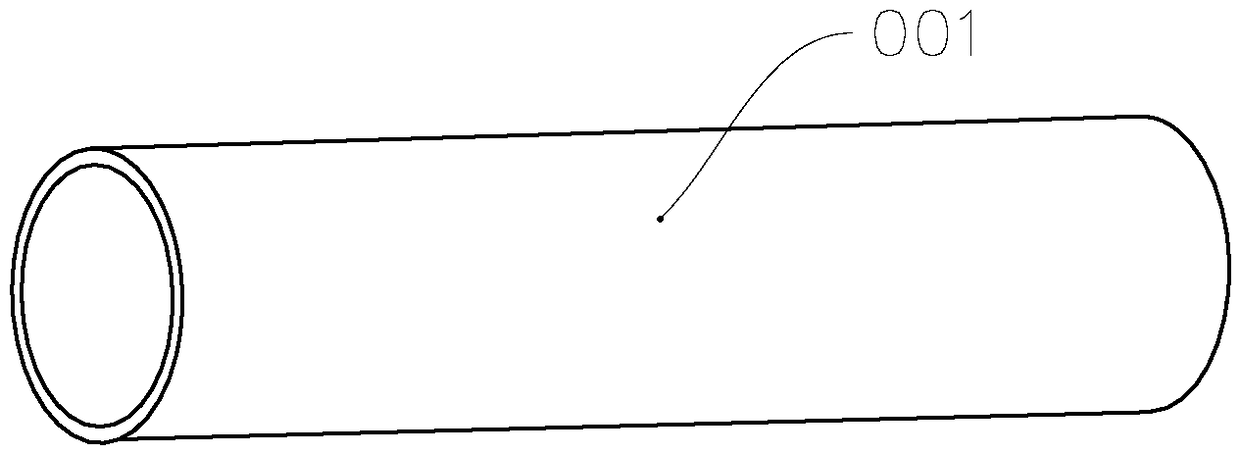
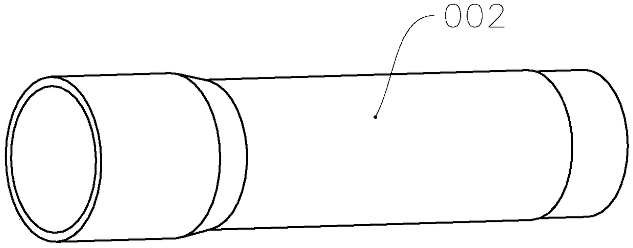
technical field [0001] The invention relates to a pipe material processing and forming equipment, in particular to a pipe section punching machine, a pipe section feeding device and pipe section processing equipment constructed with the pipe section punching machine. Background technique [0002] The four-way valve is the main component of refrigeration equipment, and its common structure is shown in the patent document with the notification number CN201391635Y, which mainly includes S connection, E connection, C connection and S connection. The structure of commonly used S takeover is as follows: figure 1 , that is, the S connection pipe 01 is provided with a bypass hole 013 at a predetermined position on the pipe body 010, and one end 011 of the pipe body 010 is narrowed, and the other end 012 is flared to match the connecting pipes at both ends road. [0003] In the process of manufacturing S pipe, the long pipe material is usually cut into such figure 2 For the short...

Claims


Application Information

Patent Timeline
IPC IPC(8): B21D28/28B21D43/02B21D43/08B21D45/06B08B5/02B23P23/04
CPCB08B5/02B21D28/28B21D43/02B21D43/08B21D45/06B23P23/04
Inventor 张良段冰
Owner 浙江长兴和良智能装备有限公司
Why Eureka
Try Eureka