Chair plate punching die replacing system

A punching and mold technology, applied in the field of seat seat plate punching mold mold change system, can solve the problems of large screw and screw hole loss, heavy mold weight, large impact force, etc., to ensure the punching quality and process Safety, reduce adjustment time effect

Inactive Publication Date: 2018-11-16
浙江恋尚家居品有限公司
View PDF0 Cites 0 Cited by
  • Summary
  • Abstract
  • Description
  • Claims
  • Application Information

AI Technical Summary

Problems solved by technology

Due to the wide variety of seat boards, frequent mold changes are required, and the weight of the mold is heavy. Manual mold change is time-consuming and labor-intensive, and there are hidden dangers of crushing and top damage; the screw-fixed clamping method requires a few points of the mold to be stressed, and punching The impact force during the hole process is large, the mold is easily damaged by extrusion deformation, and the punching quality cannot be effectively guaranteed; frequent mold changes, large loss of screws and screw ports, and reduced service life

Method used


Image

  • Chair plate punching die replacing system
  • Chair plate punching die replacing system
  • Chair plate punching die replacing system

Examples


Embodiment Construction

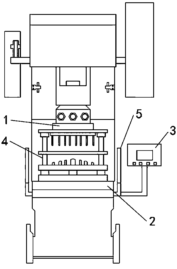
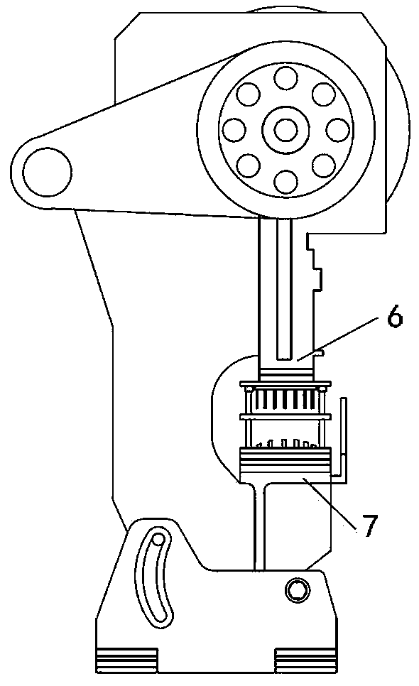
[0016] as attached figure 1 As shown, a mold change system for seat seat plate punching dies, including electro-permanent magnetic chuck I1, electro-permanent magnetic chuck II2 and electro-permanent magnetic chuck controller 3, said electro-permanent magnetic chuck I1 is fixed with punch slider 6 , the permanent magnetic chuck II2 is fixed to the punch table 7, the electro-permanent magnetic chuck controller 3 is arranged on one side of the punch table 7; a punching hole is placed between the electro-permanent magnetic chuck I1 and the electro-permanent magnetic chuck II2 Die 4; the electric permanent magnetic chuck controller 3 is respectively connected with the electric permanent magnetic chuck I1, the electric permanent magnetic chuck II2 and the circuit of the punch press control cabinet, and the punch press control cabinet is connected with a pedal circuit switch. A safety grating 5 is arranged on the front side of the punch table 7, and the safety grating 5 is composed ...


PUM


Abstract

The invention discloses a chair plate punching die replacing system which comprises an electric permanent magnetic chuck I, an electric permanent magnetic chuck II and an electric permanent magnetic chuck controller. The electric permanent magnetic chuck I is fixed to a sliding block of a punching machine. The electric permanent magnetic chuck II is fixed to a working table of the punching machine. The electric permanent magnetic chuck controller is arranged on one side of the punching machine. A punching die is arranged between the electric permanent magnetic chuck I and the electric permanent magnetic chuck II. The electric permanent magnetic chuck controller is in line connection with the electric permanent magnetic chuck I, the electric permanent magnetic chuck II and a control cabinetof the punching machine. The control cabinet of the punching machine is connected with a pedal line switch. According to the system, magnetizing of the electric permanent magnetic chucks is utilizedfor attracting an upper die plate and a lower die plate of a die to lock the die, locking is fast, fastening is firm, the machining process is safe, damage to the die is avoided, and the quality of achair plate hole position machined through punching is ensured. While time for adjusting is shortened, the punching quality of the chair plate and the service life of the die are guaranteed, and it isensured that safety accidents like crushing injuries are avoided when the punching machine carries out punching on the chair plate.

Description

technical field [0001] The invention relates to the field of furniture production, in particular to a mold changing system for a seat seat plate punching mold. Background technique [0002] At present, the hole position of the seat plate is processed by punching the mold on the punching machine with a punching needle. The original mold changing method uses manual mold changing, and the mold locking is fixed by screws, that is, several people hold the mold to the punching machine together. On the workbench, after adjusting the position correctly, use screws to fix the upper and lower templates of the mold on the workbench respectively, raise the upper template, insert the seat plate on the seat plate of the mold, and step on the foot switch after the clamping is not loose. , the punching of the upper template can be used to process the hole position of the seat plate. Due to the wide variety of seat boards, frequent mold changes are required, and the weight of the mold is he...

Claims


Application Information

Patent Timeline
Patent Type & Authority Applications(China)
IPC IPC(8): B21D37/14B21D55/00
CPCB21D37/14B21D55/00
Inventor 肖明君
Owner 浙江恋尚家居品有限公司
Why Eureka
Try Eureka