
Stirring head for friction stir welding of fillet joint

A technology of friction stir and fillet joints, which is applied in the field of stirring head of friction stir welding of fillet joints, can solve the problems of complex operation and small application range, and achieve the effect of simple operation process, wide application range and compact material filling

Active Publication Date: 2018-11-16
佳创机械设备制造(固安)有限公司
View PDF11 Cites 11 Cited by
  • Summary
  • Abstract
  • Description
  • Claims
  • Application Information

AI Technical Summary

Problems solved by technology

[0006] The purpose of the present invention is to provide a stirring head for friction stir welding of corner joints, so as to solve the technical problems in the prior art that the tool for friction stir welding of corner joints is complicated to operate and has a small scope of application

Method used


Image

  • Stirring head for friction stir welding of fillet joint
  • Stirring head for friction stir welding of fillet joint
  • Stirring head for friction stir welding of fillet joint

Examples


Embodiment Construction

[0026] In order to make the purpose, technical solution and advantages of the present invention clearer, the technical solution of the present invention will be described in detail below. Apparently, the described embodiments are only some of the embodiments of the present invention, but not all of them. Based on the embodiments of the present invention, all other implementations obtained by persons of ordinary skill in the art without making creative efforts fall within the protection scope of the present invention.

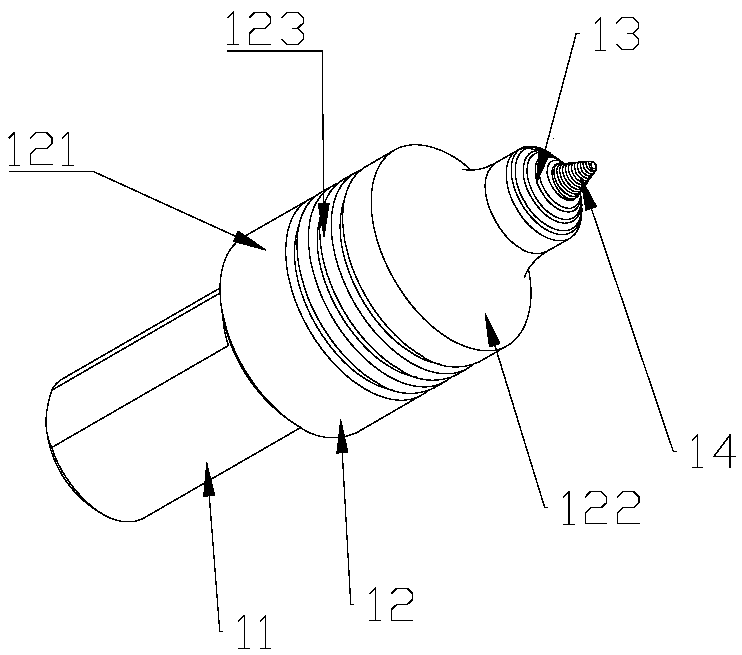
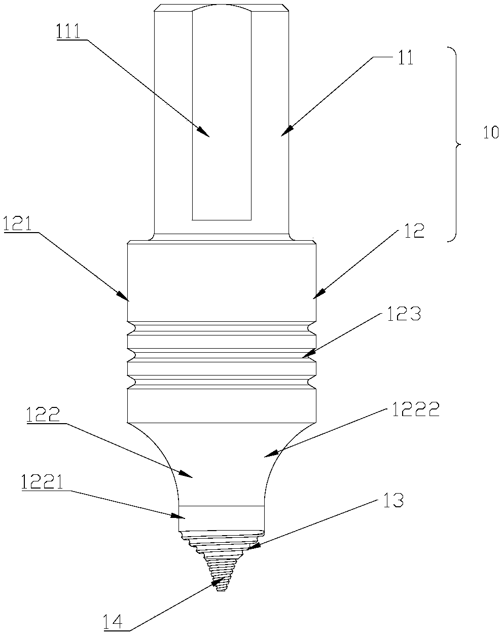
[0027] The invention provides a stirring head for friction stir welding of fillet joints, such as figure 1 and figure 2 shown, where figure 1 A schematic diagram of the three-dimensional structure of the stirring head for friction stir welding of fillet joints according to the present invention is shown; figure 2 A structural schematic view showing another perspective of the stirring head used for friction stir welding of fillet joints according to the pres...


PUM

PropertyMeasurementUnit
angleaaaaaaaaaa
depthaaaaaaaaaa
distanceaaaaaaaaaa

Abstract

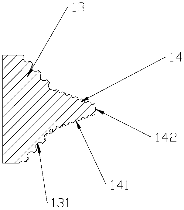
The invention provides a stirring head for friction stir welding of a fillet joint, relates to the technical field of friction stir welding, and solves technical problems in the prior art that a toolfor friction stir welding of a fillet joint is complicated in operation and small in application range. The stirring head comprises a connecting head, a shaft shoulder (13) and a stirring pin (14), wherein the shaft shoulder (13) and the stirring pin (14) are sequentially arranged below the connecting head; the shaft shoulder (13) is arranged in the way that the diameter of the shaft shoulder is gradually reduced from a connecting face with the connecting head to a direction of the stirring pin (14); and a spiral groove (131) is formed in a side surface of the shaft shoulder (13) from the connecting face with the connecting head to the direction of the stirring pin (14). The stirring head is of a simple integrated structure, and solves the problem of much assembly demand caused by use of astatic shaft shoulder stirring head; and by use of the stirring head provided by the invention, a plate to be welded does not need to be specially machined and is directly spliced into the fillet joint for welding.

Description

technical field [0001] The invention relates to the technical field of friction stir welding, in particular to a stirring head for friction stir welding of fillet joints. Background technique [0002] Since friction stir welding came out in the early 1990s, because it is particularly suitable for welding non-ferrous metals such as aluminum alloys, friction stir welding technology has continued to develop. Friction stir welding is a solid-phase welding method, which has the advantages of high joint quality, high welding efficiency, environmental protection, and low cost. It is known as another welding technology revolution after laser welding. However, any technology is not omnipotent and has its adaptability. Friction stir welding requires rigid support and firm clamping during the welding process. It is not suitable for fillet joints and space welding, and is not suitable for high melting point metals. It requires assembly accuracy. High disadvantage. [0003] The applica...

Claims


Application Information

Patent Timeline
Patent Type & Authority Applications(China)
IPC IPC(8): B23K20/12
CPCB23K20/1255
Inventor 蒋亮孔德凝
Owner 佳创机械设备制造(固安)有限公司
Learn More