Coaxiality adjusting-correcting method for long shaft coupler

A coupling and coaxiality technology, used in the field of long shaft coupling coaxiality adjustment, can solve the problem of torque reduction, unsuitable for transmitting high revolutions, high torque, difficult to erect dial indicators, etc. question

Inactive Publication Date: 2018-11-16
CHINA METALLURGICAL CONSTR ENG GRP
View PDF5 Cites 4 Cited by
  • Summary
  • Abstract
  • Description
  • Claims
  • Application Information

AI Technical Summary

Problems solved by technology

However, the above adjustment method is only applicable to the situation where the half-couplings on both sides are directly connected. Sometimes when the metallurgical system rotating mechanical equipment is installed, the half-couplings on both sides are not directly connected, and there is usually a connecting shaft between them. , usually the matching connecting shaft adopts a cardan shaft, but the cardan shaft is not suitable for transmitting high speed and high torque due to its own defects, and the transmitted torque will be greatly reduced, so after production practice, there are Some manufacturers have chosen to change the cardan shaft to a rigid straight shaft
The selection of the rigid straight shaft greatly improves the coaxiality requirements of the coupling. Before use, connect the two halves of the coupling to the output shaft of the motor and the input shaft of the reducer, and then correct the gap between the coupling halves on both sides. Coaxiality, but us...

Method used


Image

  • Coaxiality adjusting-correcting method for long shaft coupler

Examples


Embodiment Construction

[0033] The present invention will be further described below in conjunction with the accompanying drawings and embodiments.

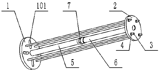
[0034]A method for adjusting the coaxiality of a long-axis coupling. Before installing a connecting shaft between two half-couplings arranged at relative intervals, an adjustment method is set between the first half-coupling and the second half-coupling. Calibration device, the calibration device is connected with the first half-coupling, and forms an alternative plane at the end facing the second half-coupling. Parallel, a dial indicator is set on the basis of the replacement plane, and the first half coupling is rotated, the rotation of the first coupling drives the replacement plane to rotate coaxially, and the dial indicator is perpendicular to the end surface to be detected on the second half coupling and The contact is measured against the end face to be tested, and the axial deviation between the corresponding end faces of the first half coupling...


PUM


Abstract

The invention discloses a coaxiality adjusting-correcting method for a long shaft coupler. The adjusting-correcting method comprises the following steps that an adjusting-correcting device is arrangedbetween a first half-coupler and a second half-coupler before a connecting shaft is arranged between the two half-couplers which are oppositely arranged at intervals; the adjusting-correcting deviceis connected with the first half-coupler, and an alternative plane is formed at one end, facing the second half-coupler, of the adjusting-correcting device; the alternative plane is parallel to the measuring reference end surface of the first half-coupler facing towards the second half-coupler, and the alternative plane can be driven to rotate coaxially when the first half-coupler rotates; and a dial indicator is arranged on the basis of taking the alternative plane as a reference, the coaxiality between the two half-couplers is measured through the dial indicator, and if the coaxiality does not reach the standard, the first half-coupler and/or the second half-coupler is moved and adjusted to the position where the coaxiality between the two half-couplers reaches the standard. By means ofthe arrangement of the alternative plane, the problem that in the prior art, the distance between two half-couplers are too long and therefore, the measurement cannot be directly carried out through adial indicator is solved, then the coaxiality between the two half-couplers can be conveniently and rapidly measured, and measurement data support is provided for adjustment and correction.

Description

technical field [0001] The invention relates to the technical field of long-axis couplings, in particular to a method for adjusting the coaxiality of long-axis couplings. Background technique [0002] In the installation project of metallurgical machinery and equipment, especially the installation of large-scale rotating machinery and equipment, the requirements for the coaxiality of the drive shaft of the motor and reducer are very strict. According to the general requirements of the national standard "GB50231-2009", the installation accuracy of the radial displacement of the two axes must be controlled within 0.05mm, and the inclination of the two axes must be controlled within 0.05 / 1000. And theoretically speaking, the higher the coaxiality adjustment accuracy of the coupling, the lower the vibration and noise generated when the equipment rotates, which can effectively prolong the service life of the bearings and bearing bushes and improve the safety of the equipment duri...

Claims


Application Information

Patent Timeline
IPC IPC(8): B23P19/10G01B5/252
CPCB23P19/10G01B5/252
Inventor 朱广军武炜朱雪威甘性禄
Owner CHINA METALLURGICAL CONSTR ENG GRP
Why Eureka
Try Eureka