
Crystal oscillator probe structure and evaporation plating device

A crystal probe, crystal oscillator technology, applied in measurement devices, electrical devices, vacuum evaporation coating, etc., can solve problems such as high cost, high rate of increase in crystal thickness, and inability to meet production needs, and achieve extended service life, monitoring and control. The effect of improved accuracy and reduced frequency drop rate

Active Publication Date: 2018-11-16
BOE TECH GRP CO LTD +1
View PDF10 Cites 5 Cited by
  • Summary
  • Abstract
  • Description
  • Claims
  • Application Information

AI Technical Summary

Problems solved by technology

For the current structure of the crystal oscillator probe, the thickness of the crystal oscillator plate increases at a high rate, resulting in a rapid decline in the monitoring accuracy of the crystal oscillator probe, requiring frequent replacement of the crystal oscillator plate, which is costly and cannot meet production needs.

Method used


Image

  • Crystal oscillator probe structure and evaporation plating device
  • Crystal oscillator probe structure and evaporation plating device
  • Crystal oscillator probe structure and evaporation plating device

Examples


Embodiment Construction

[0031] In order to make the purpose, technical solutions and advantages of the embodiments of the present disclosure clearer, the technical solutions of the embodiments of the present disclosure will be clearly and completely described below in conjunction with the accompanying drawings of the embodiments of the present disclosure. Apparently, the described embodiments are some of the embodiments of the present disclosure, not all of them. Based on the described embodiments of the present disclosure, all other embodiments obtained by persons of ordinary skill in the art without creative effort fall within the protection scope of the present disclosure.

[0032] Unless otherwise defined, the technical terms or scientific terms used in the present disclosure shall have the usual meanings understood by those skilled in the art to which the present disclosure belongs. "First", "second" and similar words used in the present disclosure do not indicate any order, quantity or importan...


PUM

PropertyMeasurementUnit
diameteraaaaaaaaaa
diameteraaaaaaaaaa

Abstract

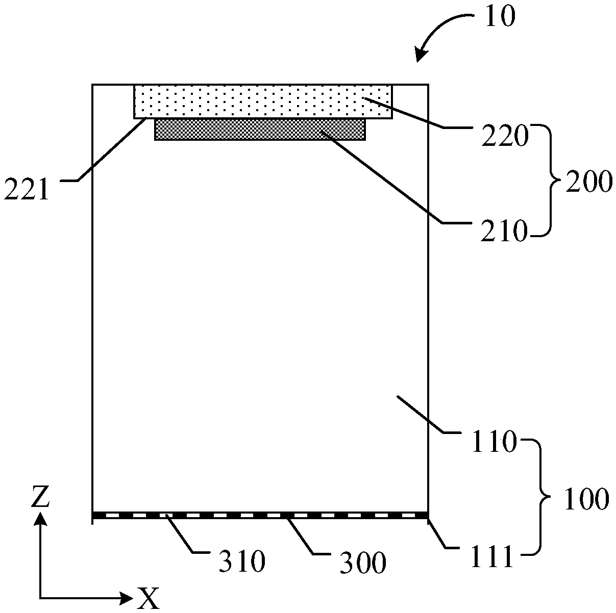
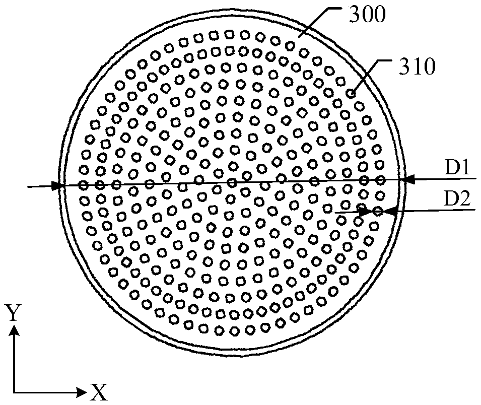
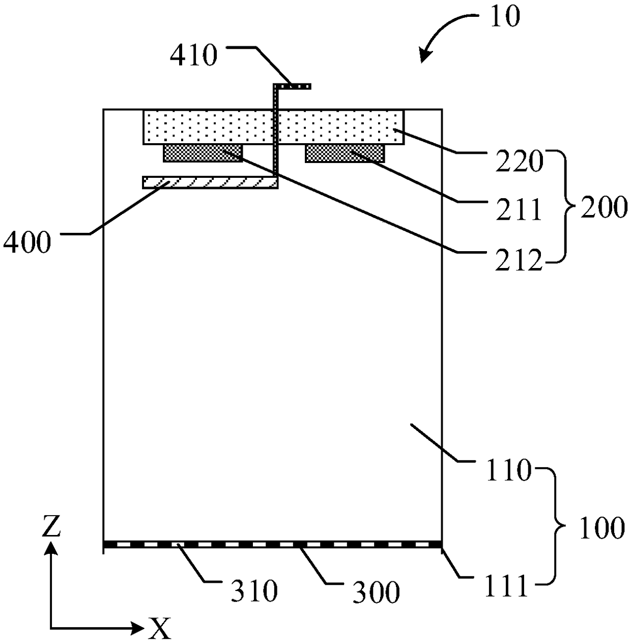
A crystal oscillator probe structure and an evaporation plating device. The crystal oscillator probe structure includes a flow guiding cover, a crystal oscillator head, and a mesh screen structure, wherein the flow guiding cover includes a chamber having a flow guiding port that is used for communicating the chamber with the exterior; the crystal oscillator head is fixed in the chamber and includes at least crystal oscillator chip; the mesh screen structure includes a plurality of holes, and is arranged on the flow guiding cover and located at one side, faced to the flow guiding port, of the crystal oscillator head. During application of the crystal oscillator probe structure, the mesh screen structure can reduce the reduction speed of frequency of the crystal oscillator chip and prolong the service life of same, thereby increasing monitoring precision of the crystal oscillator probe structure.

Description

technical field [0001] At least one embodiment of the present disclosure relates to a crystal oscillator probe structure and an evaporation device. Background technique [0002] In recent years, electronic display products such as mobile phones with organic light-emitting displays (OLEDs) have been widely recognized by users, and OLEDs can be made into flexible screens or even foldable screens, which have great development prospects. The core light-emitting part of the OLED (such as the organic light-emitting functional layer) is formed by an evaporation process, so it is very important to control the film thickness of the organic light-emitting functional layer. [0003] During the evaporation process, the crystal oscillator structure is usually used to monitor the film thickness of the organic light-emitting functional layer. The crystal oscillator in the crystal oscillator structure will also be evaporated on the crystal plate to form the organic light-emitting functional...

Claims


Application Information

Patent Timeline
Patent Type & Authority Applications(China)
IPC IPC(8): C23C14/54C23C14/24H10N30/88
CPCC23C14/24C23C14/546G01N29/12G01N2291/0256G01N2291/02854G01N29/2443G01B17/02G01B7/066H10K71/00H10N30/883
Inventor 杨一帆曹鹏赵明卿万梅
Owner BOE TECH GRP CO LTD
Learn More