
Double-beam walking-type bridge girder erection machine used for box girder erection and compatible with G-series high-speed train single-line and double-line girder erection

A double-girder walking type and bridge erecting machine technology, which is applied in the direction of erecting/assembling bridges, bridge construction, bridges, etc., to achieve the effect of improving utilization rate, improving adaptability and work efficiency

Pending Publication Date: 2018-11-16
徐州徐工铁路装备有限公司
View PDF5 Cites 7 Cited by
  • Summary
  • Abstract
  • Description
  • Claims
  • Application Information

AI Technical Summary

Problems solved by technology

[0007] In order to overcome the shortcomings of the above-mentioned prior art, the present invention provides a double girder walking bridge erecting machine compatible with high-speed rail single and double line girder erection for box girder erection. The bridge erecting machine is driven by the drive system installed in the outrigger mechanism The machine arm moves forward to pass through the hole, and the change in the principle of passing through the hole effectively solves the construction problem of complex working conditions and improves the adaptability and work efficiency of the equipment.

Method used


Image

  • Double-beam walking-type bridge girder erection machine used for box girder erection and compatible with G-series high-speed train single-line and double-line girder erection
  • Double-beam walking-type bridge girder erection machine used for box girder erection and compatible with G-series high-speed train single-line and double-line girder erection
  • Double-beam walking-type bridge girder erection machine used for box girder erection and compatible with G-series high-speed train single-line and double-line girder erection

Examples


Embodiment Construction

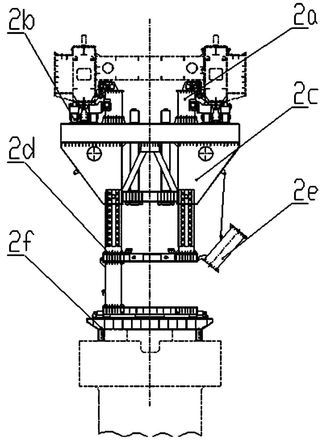
[0045] Such as Figure 1 to Figure 16 A double girder walking bridge erecting machine shown for box girder erection compatible with high-speed rail single and double wire girders includes a main girder 1, outriggers, a crane, an electric control system 8, a hydraulic system 9 and a power system 10, and its It is characterized in that: the outriggers include front outriggers 2, middle outriggers 3, through-hole outriggers 4 and rear outriggers 5, the crown block includes front crown block 6 and rear crown block 7; the main beam 1 It is composed of two parallel box girders 1b connected with the front tie beam 1a, middle tie beam 1c and rear tie beam 1e; the outer sides of the front tie beam 1a, middle tie beam 1c and rear tie beam 1e of the main beam 1 are respectively There are front outrigger installation positions, middle outrigger installation positions and rear outrigger installation positions; the front outriggers 2, middle outriggers 3 and rear outriggers 5 are sequential...


PUM


Abstract

The invention relates to a double-beam walking-type bridge girder erection machine used for box girder erection and compatible with G-series high-speed train single-line and double-line girder erection and belongs to the technical field of bridge girder erection machines. The bridge girder erection machine comprises main beams, supporting legs, overhead travelling cranes, an electric control system, a hydraulic system and a power system and is characterized in that the supporting legs include a front supporting leg, a middle supporting leg, a via hole supporting leg and a rear supporting leg,the overhead travelling cranes include a front overhead travelling crane and a back overhead travelling crane, the front supporting leg, the middle supporting leg and the rear supporting leg are sequentially connected and arranged at a main beam supporting leg installing position, a middle supporting leg installing position and a rear supporting leg installing position. The double-beam walking-type bridge girder erection machine has the advantages that a walking-type structure form is adopted, the construction problem under complicated working conditions is solved, and the adaptability and working efficiency of the machine are improved; the bottom of the front supporting leg and the bottom of the via hole supporting leg are both provided with transverse moving mechanisms, and constructionof a curve R smaller than 2000 m is really solved; the machine is compatible with G-series high-speed train single-line and double-line box girders, and the utilization rate of the machine is improved.

Description

technical field [0001] The invention relates to a double girder walking bridge erecting machine compatible with high-speed rail single and double wire girder erection for box girder erection, belonging to the technical field of bridge erection machines. Background technique [0002] So far, among the bridge erecting machines used for the erection of precast concrete box girders with a capacity of more than 550 tons in the construction of high-speed railways, according to their walking forms, there are tire-type walking and wheel-rail walking structures, and there is no double-girder walking structure bridge erecting machine. used in this field. At present, there are mainly the following problems in the tire-type traveling and wheel-rail traveling structure bridge erecting machines: [0003] 1) The slope adaptability is poor, especially in the face of large slope construction, and the safety risk is high. The reason is that the tire-type walking and wheel-rail walking struc...

Claims


Application Information

Patent Timeline
IPC IPC(8): E01D21/06
CPCE01D21/06Y02P70/10
Inventor 贾体锋张强宋健
Owner 徐州徐工铁路装备有限公司
Learn More