
Deep foundation pit soil withdrawing equipment and construction method

A construction method and technology for deep foundation pits, which are applied in basic structure engineering, excavation, lifting devices, etc., can solve the problems of earthwork excavation speed affecting lining construction progress, high risk of borrowing from deep pits, and large excavation volume. , to achieve the effect of saving labor and material resources, improving soil borrowing efficiency and high work efficiency

Inactive Publication Date: 2018-11-16
1ST ENG OF CHINA ZHONGTIE MAJORBRIDGE GROUP +1
View PDF5 Cites 1 Cited by
  • Summary
  • Abstract
  • Description
  • Claims
  • Application Information

AI Technical Summary

Problems solved by technology

The anchorage needs to excavate about 280,000 cubic meters of earthwork. The excavation volume is huge, and the risk of soil extraction from deep pits is high. Since the lining construction and earthwork excavation are carried out at the same time, the later earthwork excavation speed is too slow, which will directly affect the lining construction. schedule
Therefore, there is a need for a soil-taking equipment and construction method that can overcome the slow problem of traditional mechanical soil-taking in large-scale deep foundation pit excavation and soil-taking engineering, and improve soil-taking and construction efficiency.

Method used


Image

  • Deep foundation pit soil withdrawing equipment and construction method
  • Deep foundation pit soil withdrawing equipment and construction method
  • Deep foundation pit soil withdrawing equipment and construction method

Examples


Embodiment Construction

[0030] The present invention will be further described in detail below in conjunction with the accompanying drawings and specific embodiments.

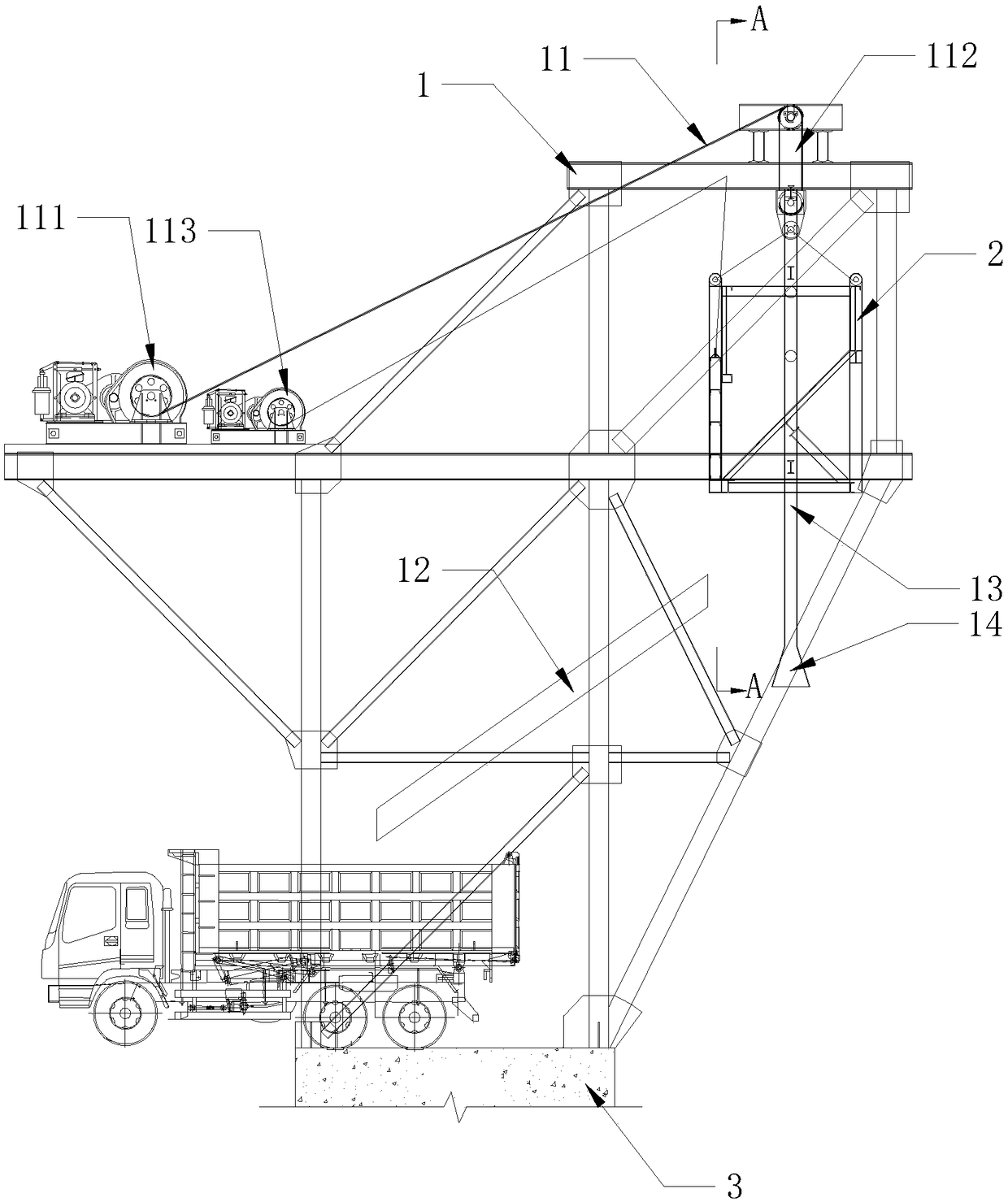
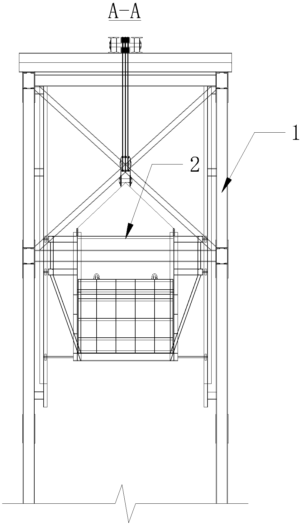
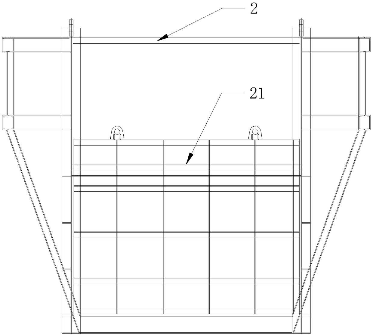
[0031] see Figure 1 to Figure 4 As shown, the embodiment of the present invention provides a deep foundation pit soil extraction equipment, including:

[0032] The lifting frame 1 fixedly arranged above the foundation pit cap beam 3, the upper part of the lifting frame 1 is provided with a lifting mechanism 11;

[0033] The hoisting bucket 2 that moves up and down is driven by the lifting mechanism 11, and an openable sliding door 21 is provided on one side of the hoisting bucket 2;

[0034] A chute 12 for soil sliding is provided on the middle part of the lifting frame 1 on a side close to the sliding door 21 .

[0035] A deep foundation pit soil extraction equipment of the present invention, the lifting frame 1 is set on the foundation pit cap beam 3, fully considers the self-weight of the lifting frame 1, the load of the hanging...


PUM


Abstract

The invention discloses deep foundation pit soil withdrawing equipment and a construction method. The deep foundation pit soil withdrawing equipment comprises a lifting frame and a lifting hopper, wherein the lifting frame is fixedly arranged on a foundation pit cap beam; a lifting mechanism is arranged at the upper part of the lifting frame; the lifting hopper is driven to move up and down by virtue of the lifting mechanism; one side of the lifting hopper is provided with a sliding door which can be opened and closed; and one side, close to the sliding door, of the middle part of the liftingframe is obliquely provided with a chute for a soil body to slide off. According to the deep foundation pit soil withdrawing equipment disclosed by the invention, the lifting frame is arranged on thefoundation pit cap beam; the dead weight of the lifting frame, the load of the lifting hopper, the soil, the wind load and the like are fully considered, so the deep foundation pit soil withdrawing equipment satisfies the strength of design standards and guarantees the use safety of the lifting frame; the lifting mechanism is used for driving the lifting hopper which can be opened and closed to move up and down so as to load and transfer the soil, the chute is used for conveying the soil into a transporting device to accomplish the soil withdrawing operation, the soil withdrawing process is simple, the automation degree is high, labor is saved, safe use is realized, and the work efficiency is high.

Description

technical field [0001] The invention relates to underground deep foundation pit construction equipment and a construction method of construction engineering, in particular to a deep foundation pit earth-taking equipment and a construction method. Background technique [0002] In recent years, with the rapid development of society, the building density in cities has been increasing with the advancement of modernization, and the number of large buildings has also continued to increase. The depth of underground space excavation has become deeper and deeper, and the excavation environment has become increasingly complex. Safety issues are highlighted accordingly. For example, during the construction of the Yangsigang Yangtze River Bridge in Wuhan, the south anchorage is a gravity anchorage with a diameter of 98m and a ground connection wall depth of 66m. The soil body is lined in layers and sections at the same time. The top elevation of the anchorage foundation is 24m (the ele...

Claims


Application Information

Patent Timeline
IPC IPC(8): E02D17/02B66F11/00
CPCB66F11/00E02D17/02
Inventor 李永旗韩胜利宋洪喜李智勇申世靖国旗金伟王全科崔岚岭郑康陆占锋刘超樊俊惠
Owner 1ST ENG OF CHINA ZHONGTIE MAJORBRIDGE GROUP
Learn More