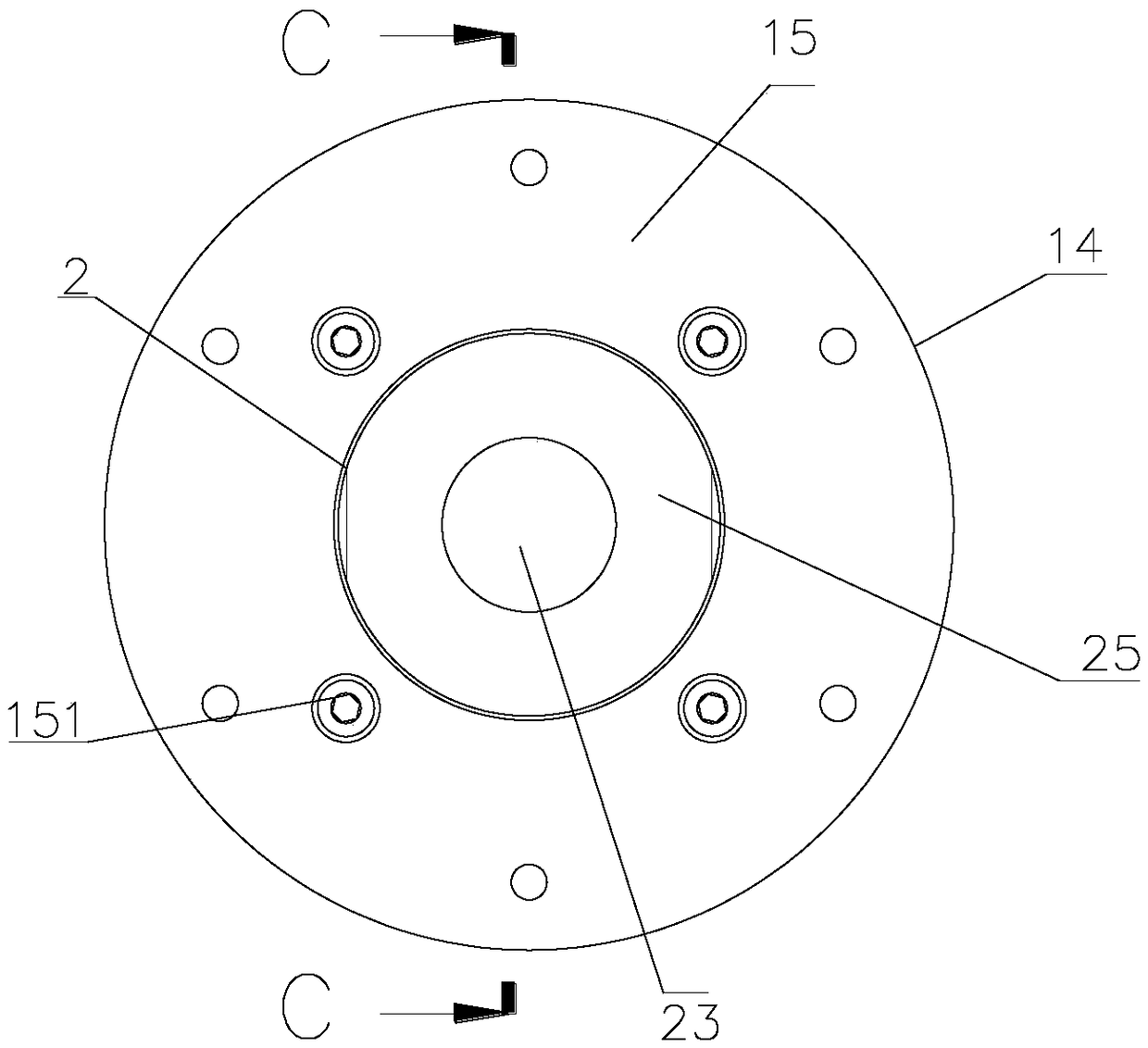
Stable and non-rotating air cylinder

A stable and cylinder technology, applied in the direction of fluid pressure actuation device, etc., can solve the problems of shortened service life, unlimited length of telescopic rod, rotation of telescopic rod body, etc.

Pending Publication Date: 2018-11-16
宁波坤易气动科技有限公司
View PDF0 Cites 0 Cited by
  • Summary
  • Abstract
  • Description
  • Claims
  • Application Information

AI Technical Summary

Problems solved by technology

However, the length adjustment of this kind of telescopic rod can only be adjusted step by step according to the interval of the interval holes, and the minimum adjustment size must be larger than the diameter of the positioning hole, so the adjustment flexibility of this kind of telescopic rod is very limited and cannot be better achieved. Practical needs
[0003] Aiming at the above defects, people set up a pneumatic cylinder, which achieves the advantages of high flexibility and convenient expansion and contraction by pneumatically controlling the telescopic rod. However, even the existing pneumatic cylinder still has the following disadvantages: 1. When the cylinder is stretching, every Since there is no guide rod for the joint telescopic rod, the telescopic rod body is prone to rotation during the telescopic process, which affects the support and transmission of items. The wear amount of the telescopic rod increases, which shortens the service life; 2. During the telescopic process of the cylinder, because there is no structure to limit the telescopic length, the length of the telescopic rod cannot be limited, and the cylinder will not be used for a long time after stretching to a certain length After that, there will be a shrinking part back, resulting in a weakening of the support

Method used


Image

  • Stable and non-rotating air cylinder
  • Stable and non-rotating air cylinder

Examples


Embodiment Construction

[0021] The specific implementation manners of the present invention will be further described below in conjunction with the accompanying drawings, so as to make the technical solution of the present invention easier to understand and grasp.

[0022] In this embodiment, it should be understood that the terms "middle", "upper", "lower", "top", "right side", "left end", "above", "back", "middle", etc. The indicated orientation or positional relationship is based on the orientation or positional relationship shown in the drawings, and is only for the convenience of describing the present invention, rather than indicating or implying that the referred device or element must have a specific orientation, be constructed and operated in a specific orientation , and therefore cannot be construed as a limitation of the present invention.

[0023] In addition, in this specific embodiment, if the connection or fixing method between the components is not specified in particular, the connect...


PUM


Abstract

The invention discloses a stable and non-rotating air cylinder. The stable and non-rotating air cylinder comprises a first-stage cylinder barrel and a second-stage cylinder barrel, wherein the second-stage cylinder barrel is arranged in the first-stage cylinder barrel and is in interactive connection with the first-stage cylinder barrel; the first-stage cylinder barrel is internally provided withfirst-stage cylinder guide rods which are used for controlling the second-stage cylinder barrel to run stably, the number of the first-stage guide rods is four, and the four first-stage guide rods arearranged in an annular array; and the second-stage cylinder barrel is provided with a rotation stopping limiting sleeve, and a stop screw is further arranged on the rotation stopping limiting sleeve.The stable and non-rotating air cylinder has the advantages that the air cylinder does not easily rotate when being used, the telescopic position of a piston rod can be fixed randomly, and the service life is long.

Description

technical field [0001] The invention specifically relates to a stable and non-rotating air cylinder. Background technique [0002] As a structural component, the telescopic rod is widely used. At present, most telescopic rods are socketed by two pipes, one of which is provided with positioning holes at intervals along the length direction, and the positioning protrusions on the other are buckled on different positioning holes to realize positioning. However, the length adjustment of this kind of telescopic rod can only be adjusted step by step according to the interval of the interval holes, and the minimum adjustment size must be larger than the diameter of the positioning hole, so the adjustment flexibility of this kind of telescopic rod is very limited and cannot be better achieved. Practical needs. [0003] Aiming at the above defects, people set up a pneumatic cylinder, which achieves the advantages of high flexibility and convenient expansion and contraction by pneum...

Claims


Application Information

Patent Timeline
Patent Type & Authority Applications(China)
IPC IPC(8): F15B15/16F15B15/26
CPCF15B15/1414F15B15/1423F15B15/16F15B15/262
Inventor 邹小燕卞立桃
Owner 宁波坤易气动科技有限公司
Why Eureka
Try Eureka