Tower signal lamp for light marking

A technology of signal lights and tower tubes, applied in the field of lighting, can solve problems such as failure of the overall protection ability of the tower wall, lack of night markings, difficulty in meeting requirements, etc., and achieve the effects of widely popularizing the use value, convenient operation and setting, and convenient calibration

Inactive Publication Date: 2018-11-16
SHANGHAI NANHUA ELECTRONICS
View PDF13 Cites 1 Cited by
  • Summary
  • Abstract
  • Description
  • Claims
  • Application Information

AI Technical Summary

Problems solved by technology

A wind park consisting of several individual wind installations is usually stretched vertically and horizontally, however, the disadvantage for air traffic around it is the lack of night markings, since these areas have to be bypassed, which is an obstacle especially for amateur flying activities
[0003] DE 103 58 962 A1 discloses a wind power installation having a tower with at least one obstacle light device emitting outwards, for which purpose the tower is provided with at least one perforation through which power lines are routed from the inside of the tower to the outside , and the luminous obstacle lighting device is fixed by the outside of the wind power equipment tower, the cost of installation and maintenance is very high
And after the tower wall is opened, the overall protection ability of the tower wall is easy to fail after the tower wall hole is installed with the tower signal light
[0004] At present, the marking device on the tower wall of the common wind power equipment is difficult to meet the requirements of ICAO Annex 14 with a horizontal light angle of 360°
[0005] EP 2 213 876 A1 discloses an obstacle light for a wind turbine equipment tower. After passing through the tower wall, the obstacle light needs to be folded up again. The structure is complex and the operation is difficult.

Method used


Image

  • Tower signal lamp for light marking
  • Tower signal lamp for light marking
  • Tower signal lamp for light marking

Examples


Embodiment 1

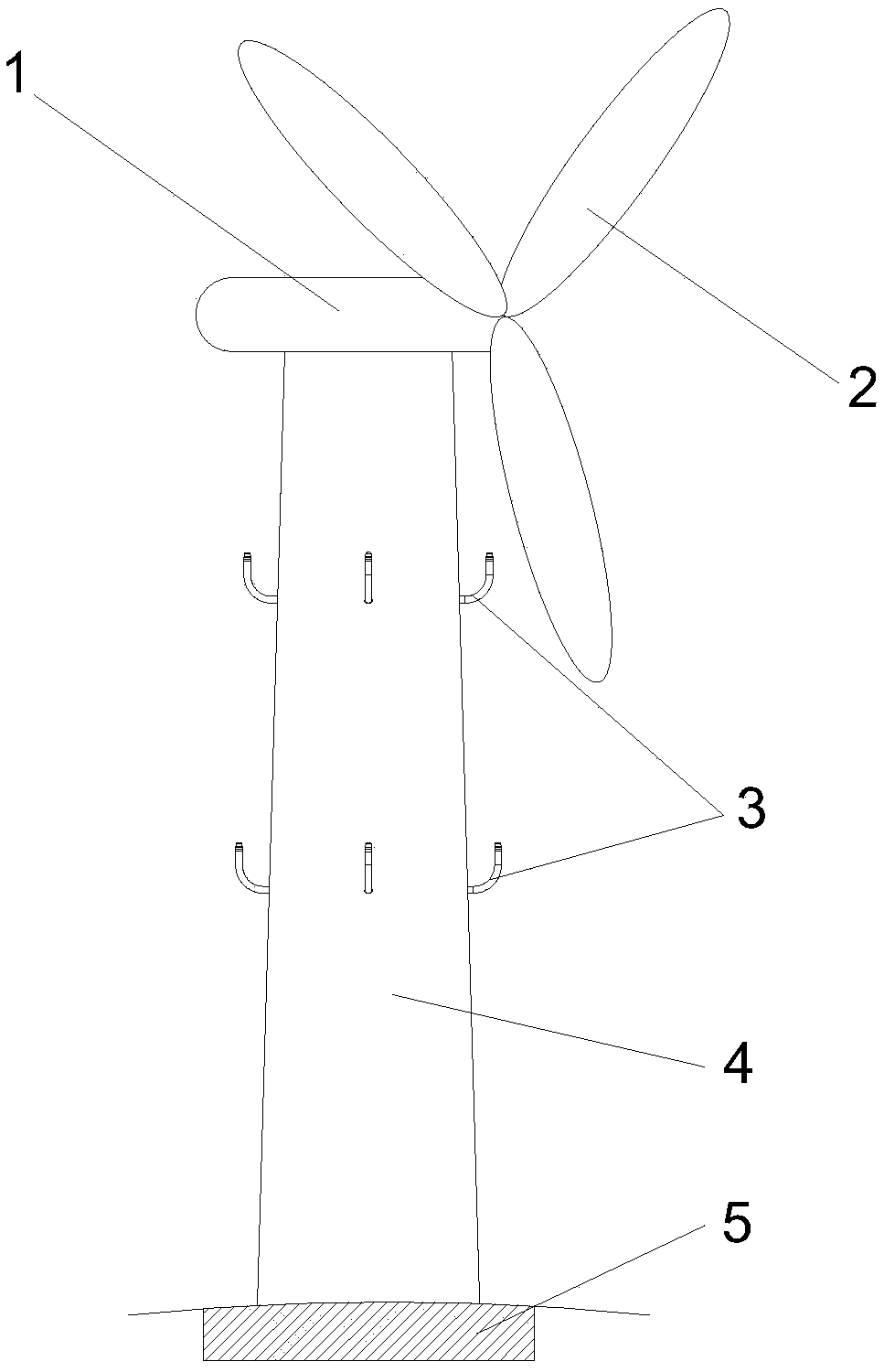
[0029] like figure 1 Shown is a schematic diagram of the overall structure of several tower tube signal lights of wind power equipment towers. The tower 4 is erected on the foundation 5, and the upper end of the tower tube 4 is provided with a mechanical pod 1 and blades 2 on the rotor arranged on the pod. Tower signal lights 3 are installed on the two tower planes of the tower tube 4, thereby playing a marking role for air traffic, so that the tower can be seen from a distance.

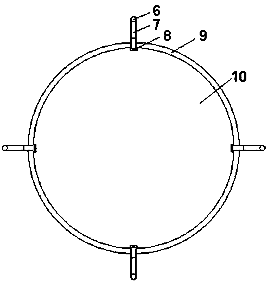
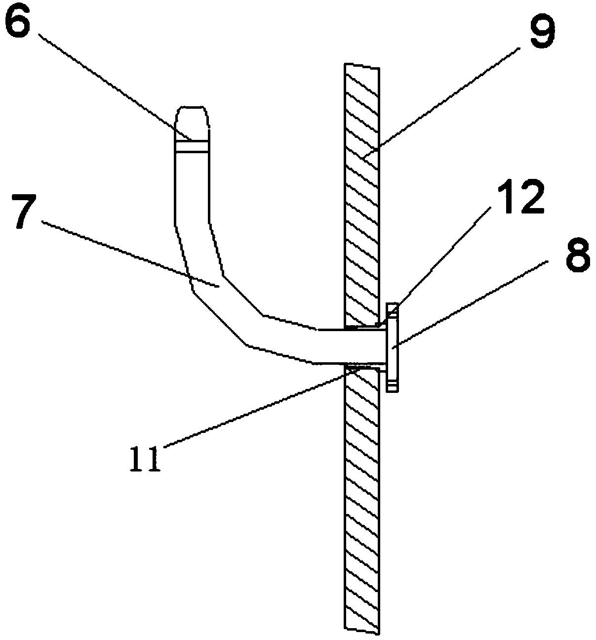
[0030] like Figure 2-4 As shown, a tower signal light for light marking of the present invention includes a right-angle elbow bracket 7, a light-emitting element 6 arranged at the first end of the right-angle elbow bracket 7, and an introduction of the second end of the right-angle elbow bracket 7. Wire wiring device (not shown in the figure); the tower wall 9 of the tower 4 is provided with a hole 11, and the right-angle elbow bracket 7 can be inserted from the tower inner wall to the tower outer ...

Embodiment 2

[0049] like Figure 2-4 As shown, a tower signal light for light marking of the present invention includes a right-angle elbow bracket 7, a light-emitting element 6 arranged at the first end of the right-angle elbow bracket 7, and an introduction of the second end of the right-angle elbow bracket 7. Wire wiring device (not shown in the figure); the tower wall 9 of the tower 4 is provided with a hole 11, and the right-angle elbow bracket 7 can be inserted from the tower inner wall to the tower outer wall through the hole 11 on the tower wall 9, and the right-angle elbow bracket The second end of 7 is fixed in the hole 11 of the tower wall 9; the light-emitting element 6 emits light to the periphery of the tower, the horizontal light-emitting angle reaches 360°, and the vertical light-emitting angle is >90°.

[0050] The tower signal lamp of the present invention is fixedly connected to the light-emitting element and the wiring device through the right-angle elbow bracket. The r...

Embodiment 3

[0066] like figure 1 Shown is a schematic diagram of the overall structure of several tower tube signal lights of wind power equipment towers. The tower 4 is erected on the foundation 5, and the upper end of the tower tube 4 is provided with a mechanical pod 1 and blades 2 on the rotor arranged on the pod. Tower signal lights 3 are installed on the two tower planes of the tower tube 4, thereby playing a marking role for air traffic, so that the tower can be seen from a distance.

[0067] like Figure 2-4 As shown, a tower signal light for light marking of the present invention includes a right-angle elbow bracket 7, a light-emitting element 6 arranged at the first end of the right-angle elbow bracket 7, and an introduction of the second end of the right-angle elbow bracket 7. Wire wiring device (not shown in the figure); the tower wall 9 of the tower 4 is provided with a hole 11, and the right-angle elbow bracket 7 can be inserted from the tower inner wall to the tower outer ...


PUM


Abstract

The invention belongs to the field of illumination, and particularly relates to a tower signal lamp for light marking. The tower signal lamp is characterized by comprising a right-angle bent tube support, a light-emitting element arranged at a first end of the right-angled bent tube support, and a lead-in wiring device arranged at a second end of the right-angle bent tube support; a hole is formedin the tower wall of a tower, and the right-angle bent tube support can be inserted into the outer wall of the tower from the inner wall of the tower through the hole in the tower wall; the second end of the right-angle bent tube support is fixed in the hole in the tower wall of the tower; the light-emitting element emits light to the periphery of the tower, the horizontal light-emitting angle reaches 360 degrees, and the vertical light-emitting angle is larger than 90 degrees. The signal lamp is convenient to install, that is, the signal lamp can be vertically erected on the horizontal planewithout redundant operation, so that the light-emitting element emits light to the periphery of the tower, the cost is low, the labor cost is saved, and the tower signal lamp has wide application andpopularization value.

Description

technical field [0001] The invention belongs to the field of lighting, and in particular relates to a tower signal lamp used for light marking. Background technique [0002] At present, the towers of common wind power equipment do not have significant night light marking devices. A wind park consisting of several individual wind installations is usually stretched vertically and horizontally, however, the disadvantage for air traffic around it is the lack of night markings, since these areas have to be bypassed, which is an obstacle especially for amateur flying activities . [0003] DE 103 58 962 A1 discloses a wind power installation having a tower with at least one obstacle light device emitting outwards, for which purpose the tower is provided with at least one perforation through which power lines are routed from the inside of the tower to the outside , and the luminous obstacle lighting device is fixed by the outside of the wind power equipment tower, and the cost of ...

Claims


Application Information

Patent Timeline
IPC IPC(8): F21S8/00F21V21/00F21V23/00F21V31/00F21V33/00F21Y115/10F21W111/00
CPCF21S8/036F21V21/00F21V23/002F21V31/005F21V33/00F21W2111/00F21Y2115/10
Inventor 肖飞黄恒
Owner SHANGHAI NANHUA ELECTRONICS
Why Eureka
Try Eureka