Smoke exhaust pipeline cleaning device

A technology for cleaning devices and smoke exhaust pipes, which is applied in the directions of cleaning hollow objects, cleaning methods and utensils, removing solid residues, etc. Pipeline smoke exhaust efficiency and other issues, to improve the convenience of cleaning, to avoid beams and columns, and to increase the efficiency of air purification

Inactive Publication Date: 2018-11-16
韩智强
View PDF5 Cites 1 Cited by
  • Summary
  • Abstract
  • Description
  • Claims
  • Application Information

AI Technical Summary

Problems solved by technology

Atmospheric conditions are changing rapidly, which has a serious impact on the smoke exhaust effect of the exhaust pipe. Although various advanced combustion control systems and energy-saving devices used in boilers, the resistance of smoke exhaust has been fully calculated, but it is impossible to estimate the effect of atmospheric flow changes. resistance
[0003] In the prior art, the existing smoke exhaust pipeline is not equipped with a cleaning device, which is inconvenient to clean the inside of the smoke exhaust pipeline. After long-term use, the smoke exhaust pipeline is prone to blockage, which affects the smoke exhaust efficiency of the smoke exhaust pipeline. The oily fume discharged from the smoke exhaust pipeline will cause air pollution to the surrounding environment, so now there is an urgent need for a cleaning device for the smoke exhaust pipeline to solve the above-mentioned problems

Method used


Image

  • Smoke exhaust pipeline cleaning device
  • Smoke exhaust pipeline cleaning device
  • Smoke exhaust pipeline cleaning device

Examples


Embodiment Construction

[0020] In order to make the technical means, creative features, goals and effects achieved by the present invention easy to understand, the present invention will be further described below in conjunction with specific embodiments.

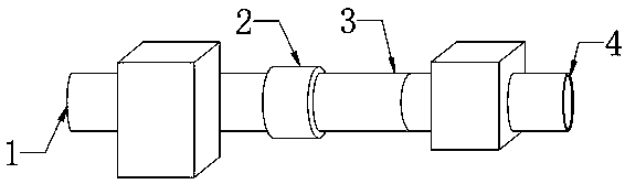
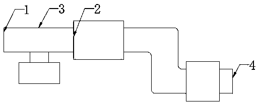
[0021] see Figure 1-Figure 3 , the present invention provides a technical solution: a cleaning device for a smoke exhaust pipeline, including a smoke inlet 1, a cleaning mechanism 2, a main body of the smoke exhaust pipeline 3 and a smoke outlet 4, and the smoke inlet 1 is set in the exhaust The left end surface of the smoke pipeline main body 3 and the right end surface of the smoke exhaust pipeline main body 3 are provided with a smoke outlet 4 , and the cleaning mechanism 2 is arranged on the annular side of the smoke exhaust pipeline main body 3 .

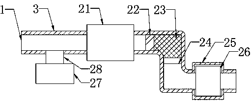
[0022] The cleaning mechanism 2 includes an oil-water separator 21, a filter screen 22, a drying box 23, an isolation net 24, an installation shell 25, a blower 26, a small electric steam generato...


PUM


Abstract

The invention provides a smoke exhaust pipeline cleaning device which comprises a smoke inlet, a smoke exhaust pipeline main body, a smoke outlet, oil-water separators, a mounting shell, an air blower, a small electric steam generator and a steam connecting pipe. The smoke inlet is formed in the left end surface of the smoke exhaust pipeline main body, the right end surface of the smoke exhaust pipeline main body is provided with a smoke outlet, and the oil-water separators are connected to the left side and the right side of the smoke exhaust pipeline main body. The mounting shell is arrangedon the outer side of the air blower, the left side and the right side of the smoke exhaust pipeline main body are connected through the air blower, and the air blower is arranged on the right side ofthe corresponding oil-water separator. A steam connecting pipe is connected to the front side of the annular side face of the smoke exhaust pipeline main body, and the front end surface of the steamconnecting pipe is connected with the small electric steam generator. Through the design, the problem that a cleaning device of an existing smoke exhaust pipeline is insufficient is solved, and the smoke exhaust pipeline cleaning device is reasonable in structure, good in cleaning effect and high in anti-blocking performance, saves energy and protects the environment.

Description

technical field [0001] The invention relates to a cleaning device for a smoke exhaust pipeline, which belongs to the field of smoke exhaust pipeline equipment. Background technique [0002] At present, the smoke exhaust pipe is the main means of discharging toxic and harmful gases in chemical enterprises and power plants, and is the main source of air pollution. In recent years, the high domestic atmospheric PM2. Stubborn illnesses and boilers with poor smoke exhaust lead to more severe air pollution. Atmospheric conditions are changing rapidly, which has a serious impact on the smoke exhaust effect of the exhaust pipe. Although various advanced combustion control systems and energy-saving devices used in boilers, the resistance of smoke exhaust has been fully calculated, but it is impossible to estimate the effect of atmospheric flow changes. resistance. [0003] In the prior art, the existing smoke exhaust pipeline is not equipped with a cleaning device, which is inconve...

Claims


Application Information

Patent Timeline
Patent Type & Authority Applications(China)
IPC IPC(8): F23J3/02B08B9/032
CPCF23J3/02B08B9/032
Inventor 韩智强
Owner 韩智强
Why Eureka
Try Eureka