Building center flue system

A flue system, central technology, applied in the direction of oil fume removal, vertical pipes, household heating, etc., can solve the problems of low operating efficiency, shortened motor life, large smoke exhaust resistance, etc., to achieve high smoke exhaust efficiency and fan life Long, low smoke exhaust resistance

Pending Publication Date: 2020-05-29
NINGBO FOTILE KITCHEN WARE CO LTD
View PDF0 Cites 2 Cited by
  • Summary
  • Abstract
  • Description
  • Claims
  • Application Information

AI Technical Summary

Problems solved by technology

Existing central flue systems in buildings only have one large flue fan installed at the outlet of the public flue. Even if only one or a few households in the whole building are turned on, the flue fan needs to be turned on frequently, resulting in The life of the motor is shortened, and the operating efficiency is low. In addition, the large flue fan is directly arranged at the flue outlet, which will lead to a large smoke exhaust resistance
In addition, in order to ensure the air pressure balance in the kitchen, there is also a kitchen air supply structure disclosed at present, but the existing kitchen air supply structure generally needs to install power at the air supply port to supplement the air, and the existing flue fan is mainly used for exhaust air. , can not be used to make up the air for the kitchen

Method used


Image

  • Building center flue system
  • Building center flue system
  • Building center flue system

Examples


Embodiment 1

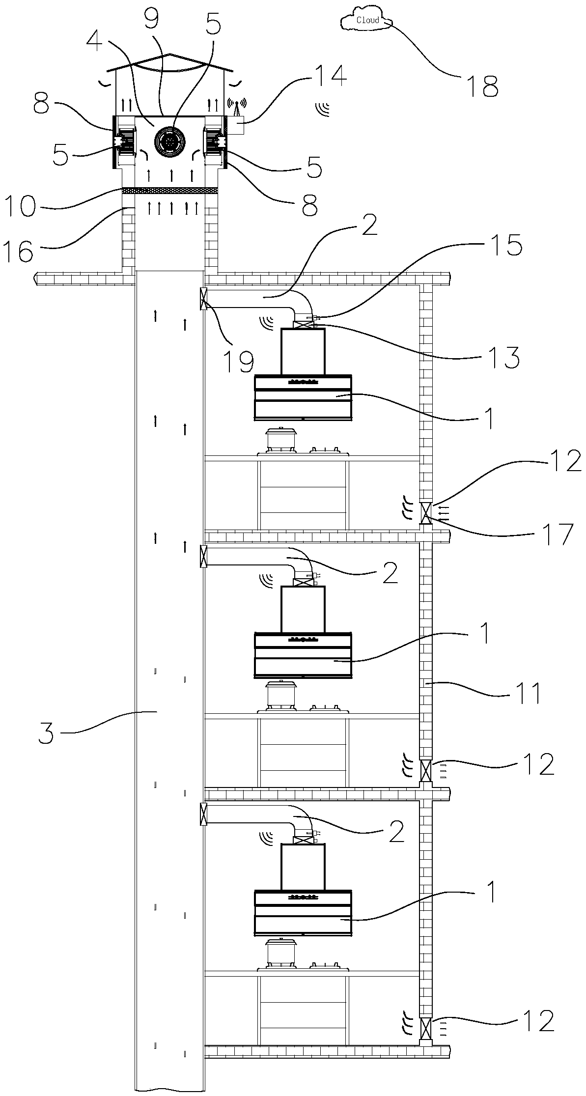
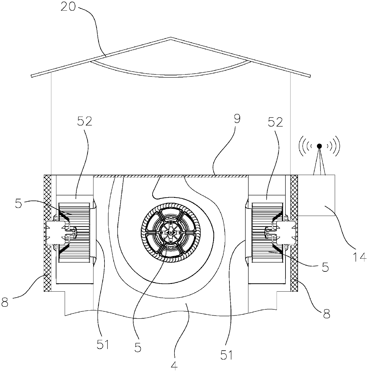
[0035] Such as Figure 1 to Figure 3 As shown, the central flue system of the building in this embodiment includes range hoods 1 installed on different floors, and the air outlets of each range hood 1 are connected with the public flue 3 through their respective smoke pipes 2. The air outlet channel 4 that is vertically connected with the outlet of the public flue 3 is installed, the aperture of the air outlet channel 4 is greater than the aperture of the public flue 3, and the flue fan 5 is located at a position close to the inner wall of the air outlet channel and avoids coming from the public air channel. The airflow discharged from the outlet of the flue 3, thereby reducing the smoke exhaust resistance of the system.

[0036] In this embodiment, the air outlet passage 4 is a square passage, and the flue fan 5 is a centrifugal fan placed vertically. The back of the flue fan 5 is close to the inner wall of the air outlet passage 4. A noise reduction and muffler device 8 is ...

Embodiment 2

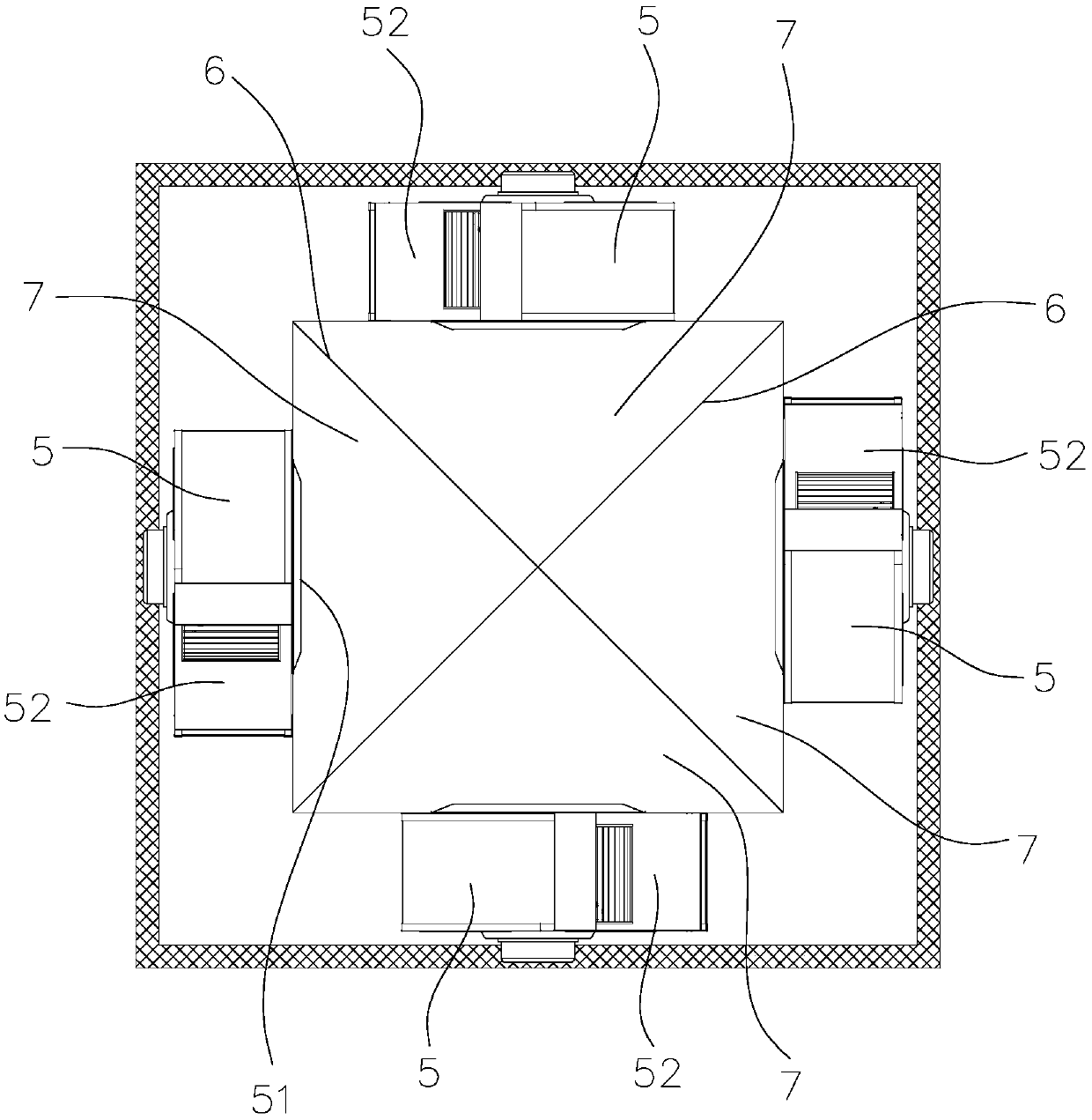
[0042] Such as Figure 4 As shown, in this embodiment, there are also four flue fans 5 in the central flue system and they are correspondingly arranged on the four side walls of the air outlet channel 4. The difference from Embodiment 1 lies in the distribution of the air duct partitions 6 different ways. In this embodiment, there are three air duct partitions 6 and are distributed in an H shape. The air duct partitions 6 divide the interior of the air outlet channel 4 into four mutually isolated air inlet areas 7, and the air outlet of each flue fan 5 Corresponding to the air inlet area 7 one by one. The rest of the structure of this embodiment is the same as that of Embodiment 1, and will not be further described here.

Embodiment 3

[0044] Such as Figure 5 As shown, in this embodiment, there are three flue fans 5 of the central flue system and are arranged on the three side walls of the air outlet channel 4, and there are two air duct partitions 6 and are distributed in a T shape. The plate 6 divides the inside of the air outlet channel 4 into three mutually isolated air inlet areas 7 , and the air outlet of each flue fan 5 corresponds to the air inlet areas 7 one by one. The rest of the structure of this embodiment is the same as that of Embodiment 1, and will not be further described here.


PUM


Abstract

Disclosed is a building center flue system. The system comprises extractor hoods installed at different floors. An air outlet of each extractor hood communicates with a public flue through a corresponding smoke tube. An air outlet channel vertically and directly communicates with an outlet of the public flue is installed on a roof. The system is characterized in that the caliber of the air outletchannel is larger than the caliber of the public flue, at least two independently-working flue fans are installed inside the air outlet channel, and the flue fans are arranged at the position close tothe inner wall of the air outlet channel so as to avoid airflow exhausted from the outlet of the public flue. The system has the advantages that outdoor smoke exhaust power of the building center flue system adopts combination of multiple fans, the flue fans are arranged at the position close to the inner wall of the air outlet channel and avoid the airflow exhausted from the outlet of the publicflue, the arrangement of the fans is more reasonable and scientific and applicable to various complex installation environments, the smoke exhaust resistance of the system is small, the system is higher in smoke exhaust efficiency, saves more energy, and is higher in reliability, and the fans are longer in service life.

Description

technical field [0001] The invention relates to a flue system, in particular to a building central flue system. Background technique [0002] At present, the floors of newly-built buildings in cities are generally getting higher and higher, and the outlets of high-rise public flues are generally set on the top of the floors. In order to ensure that the range hoods of users on each floor can exhaust smoke smoothly, a Flue fan, the flue fan is the main engine fan, when the flue fan is working, a negative pressure is formed at the outlet of the public flue, and the range hood on the user side is also equipped with a fan, so that the oil fume on the user side can pass through the public flue Ejected smoothly. Existing central flue systems in buildings only have one large flue fan installed at the outlet of the common flue. Even if only one or a few households in the whole building are turned on, the flue fan needs to be turned on frequently, resulting in The life of the motor ...

Claims


Application Information

Patent Timeline
Patent Type & Authority Applications(China)
IPC IPC(8): F24C15/20E04F17/02
CPCE04F17/02F24C15/20F24C15/2021
Inventor 梁雪斐
Owner NINGBO FOTILE KITCHEN WARE CO LTD
Why Eureka
Try Eureka