Smoke discharging system for plasma cutting machine

A technology of plasma cutting machine and fume extraction system, which is applied in the direction of plasma welding equipment, welding/cutting auxiliary equipment, auxiliary devices, etc., can solve the problems of polluting the on-site environment and physical harm of on-site operators, and achieves the effect of ensuring high efficiency

Active Publication Date: 2018-07-10
日照兴业汽车配件股份有限公司
View PDF8 Cites 2 Cited by
  • Summary
  • Abstract
  • Description
  • Claims
  • Application Information

AI Technical Summary

Problems solved by technology

[0002] In industrial production, plasma cutting machine is a commonly used processing equipment. Plasma cutting uses the heat of high-temperature plasma arc to partially or partially melt (and evaporate) the metal at the incision of the workpiece, and uses the momentum of high-speed plasma to exclude molten metal to form Cutting, plasma cutting process will produce a lot of smoke and dust, if not dealt with in time, the smoke and dust will spread into the air of the processing site, pollute the site environment, and cause harm to the health of the workers on site

Method used


Image

  • Smoke discharging system for plasma cutting machine
  • Smoke discharging system for plasma cutting machine
  • Smoke discharging system for plasma cutting machine

Examples


Embodiment 1

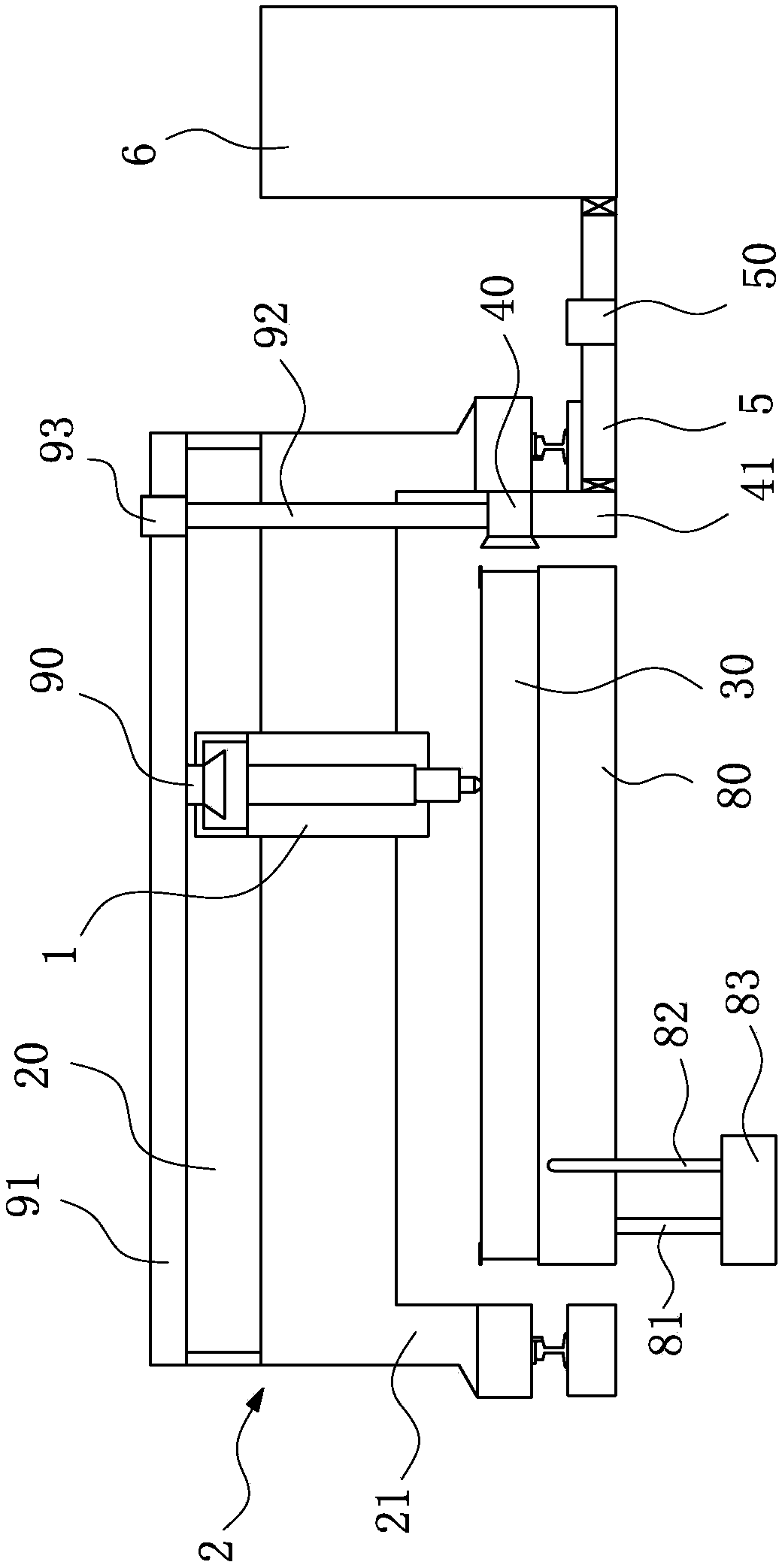
[0034] Such as figure 1 As shown, a smoke exhaust system for a plasma cutting machine. The plasma cutting machine includes a cutting head 1, a sliding frame 2, and a cutting table 3. The cutting table 3 is used to place processed products. Rails are provided on both sides of the cutting table 3. The carriage 2 includes a crossbeam 20 and support arms 21 located at both ends of the crossbeam 20. The two support arms 21 are respectively slidably mounted on the rails on both sides. The cutting head 1 is installed on the crossbeam 20 and can slide along the crossbeam 20 under the drive of the motor. That is, the displacement adjustment in the X direction and the Y direction in the horizontal plane is used to realize the adjustment of the cutting position of the cutting machine.

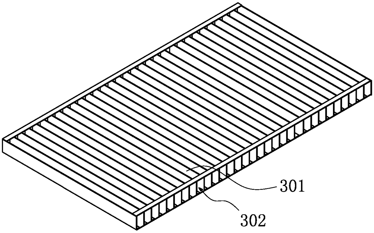
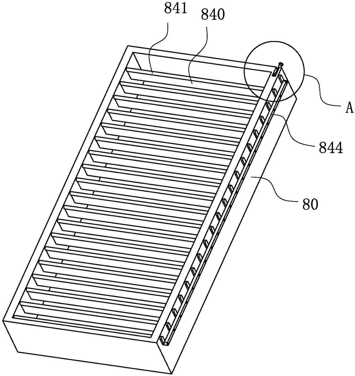
[0035] Such as figure 2 As shown, the top of the cutting table 3 is a grid 30, and the bottom is a water tank 80. The grid 30 includes a plurality of vertical partitions 301, and the plurality of vertic...

Embodiment 2

[0041] The difference between this embodiment and Embodiment 1 is that: Figure 6 As shown, one side of the smoke collection channel 302 is the air suction device 4, and the other side is the air blowing device 7, the air blowing device 7 is installed on the support arm 21, and the air outlet of the air blowing device 7 is connected to the first sliding suction end 40 The suction port is directly opposite, and the air blowing device 7 can blow the smoke to the first sliding suction end 40, so as to accelerate the collection of the smoke and dust. In this embodiment, the blowing device 7 is a light blower 50.

Embodiment 3

[0043] The difference between this embodiment and Embodiment 1 is that: Figure 7 As shown, there are two air suction devices 4, and the two air suction devices 4 are symmetrically arranged on both sides of the smoke collection channel 302, so as to strengthen the ability of the smoke exhaust system to collect smoke and dust, and avoid a single air suction device 4. Insufficient suction force causes a weak smoke collection area to be formed on the smoke collection channel 302 . In this embodiment, two suction devices 4 are connected to the same air duct 5 .


PUM


Abstract

The invention discloses a smoke discharging system for a plasma cutting machine, and relates to the technical field of smoke discharging. A grid is arranged at the upper portion of a cutting table ofthe plasma cutting machine. A plurality of vertical partition plates of the grid are arranged in the extending direction of the cutting table. A smoke gathering channel is formed between every two adjacent vertical partition plates. The smoke discharging system comprises an air suction device. The air suction device comprises a first sliding air suction end and a first sliding air flue which are used in combination, wherein the first sliding air suction end is arranged on a sliding frame, an air suction port of the first sliding air suction end is right opposite to a port of the smoke gathering channel, and the first sliding air flue is connected to a dust remover through an air pipe. The efficient smoke discharging system for the plasma cutting machine is provided. By means of the smoke discharging system, smoke generated in the plasma cutting machine cutting process can be effectively collected and treated, air cleanliness of the machining area is guaranteed, and hurt to operators from smoke is reduced.

Description

technical field [0001] The invention relates to the technical field of smoke exhaust, in particular to a smoke exhaust system for a plasma cutting machine. Background technique [0002] In industrial production, plasma cutting machine is a commonly used processing equipment. Plasma cutting uses the heat of high-temperature plasma arc to partially or partially melt (and evaporate) the metal at the incision of the workpiece, and uses the momentum of high-speed plasma to exclude molten metal to form Incision and plasma cutting process will produce a lot of smoke and dust, if not dealt with in time, the smoke and dust will spread into the air of the processing site, pollute the site environment, and cause harm to the health of the workers on site. Contents of the invention [0003] In view of the above defects, the technical problem to be solved by the present invention is to provide a smoke exhaust system for a plasma cutting machine, which can efficiently collect and process...

Claims


Application Information

Patent Timeline
Patent Type & Authority Applications(China)
IPC IPC(8): B23K10/00B23K37/00
CPCB23K10/00B23K37/00
Inventor 管恩业张志勇窦燕燕
Owner 日照兴业汽车配件股份有限公司
Why Eureka
Try Eureka