
In-process sintering machine trolley wheel automatic centering device

An automatic centering and sintering machine technology, applied in crucible furnaces, furnaces, lighting and heating equipment, etc., can solve problems such as increasing personnel overhead, shortening bearing service life, affecting material balance, etc., to improve resource utilization and reduce personnel. Cost, good economic effect

Active Publication Date: 2018-11-16
HUATIAN ENG & TECH CORP MCC
View PDF5 Cites 4 Cited by
  • Summary
  • Abstract
  • Description
  • Claims
  • Application Information

AI Technical Summary

Problems solved by technology

During the limited downtime for maintenance, the wheels of sintering machine trolleys are often not lubricated effectively
Moreover, the lubricating grease in the wheels of the sintering machine trolley has been consumed within the interval between sintering machine shutdowns.
Insufficient lubricating grease in the wheels of sintered locomotives will shorten the service life of the bearings, which in turn will affect the function of the trolley wheels
When the wheel of the trolley is stuck, it must be stopped and replaced in time, otherwise it may affect the overall operation of the sintering machine. If the trolley needs to be shut down to replace the trolley, firstly, it will affect the operation rate of the sintering machine and the output of sintering ore, resulting in Economic losses
Second, the replacement of the sintering machine trolley will affect the material balance in the sintering process. The process of re-balancing the material from unbalanced to balanced will not only affect the quality of sintered ore, but also cause unnecessary energy loss
The third is to use manual grease filling, and special maintenance personnel must be assigned to maintain the wheels, which increases personnel costs.

Method used


Image

  • In-process sintering machine trolley wheel automatic centering device
  • In-process sintering machine trolley wheel automatic centering device

Examples


Embodiment 1

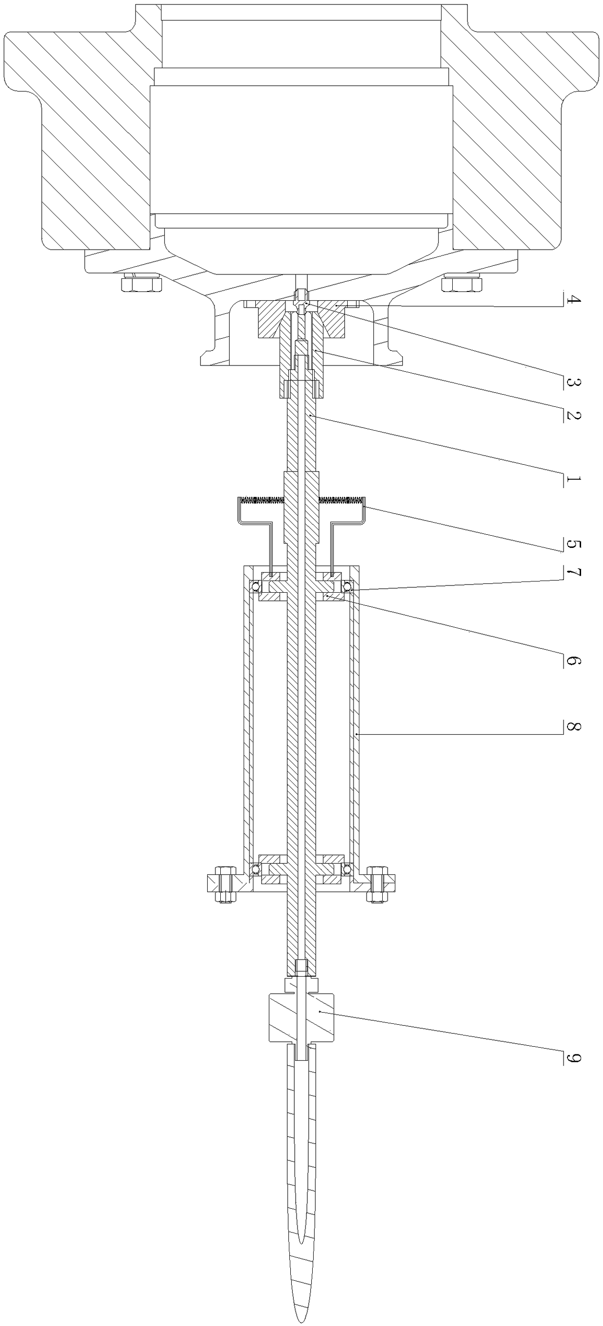
[0021] from figure 1 It can be seen that the automatic wheel centering device of a moving sintering machine in this embodiment includes a rotary shaft 1, one end of the rotary shaft 1 is provided with a shaft end joint body 2, and the front end of the shaft end joint body 2 is provided with a wheel. The outer surface of the wheel is respectively fixed with the wheel joint body 3 and the wheel positioning block 4, the shaft end joint body 2 and the wheel joint body 3 cooperate with each other, and the wheel positioning block 4 is used for guiding. direction and moving towards the wheel, under the guidance of the positioning block 4 on the wheel, the shaft end joint body 2 at the front end of the rotary shaft 1 and the wheel joint body 3 located on the wheel perform mutual sealing cooperation, and the shaft end joint body 2 can To adapt to the direction deviation of the wheel, ensure that the lubricating grease can be injected into the inside of the wheel under pressure. The oth...


PUM


Abstract

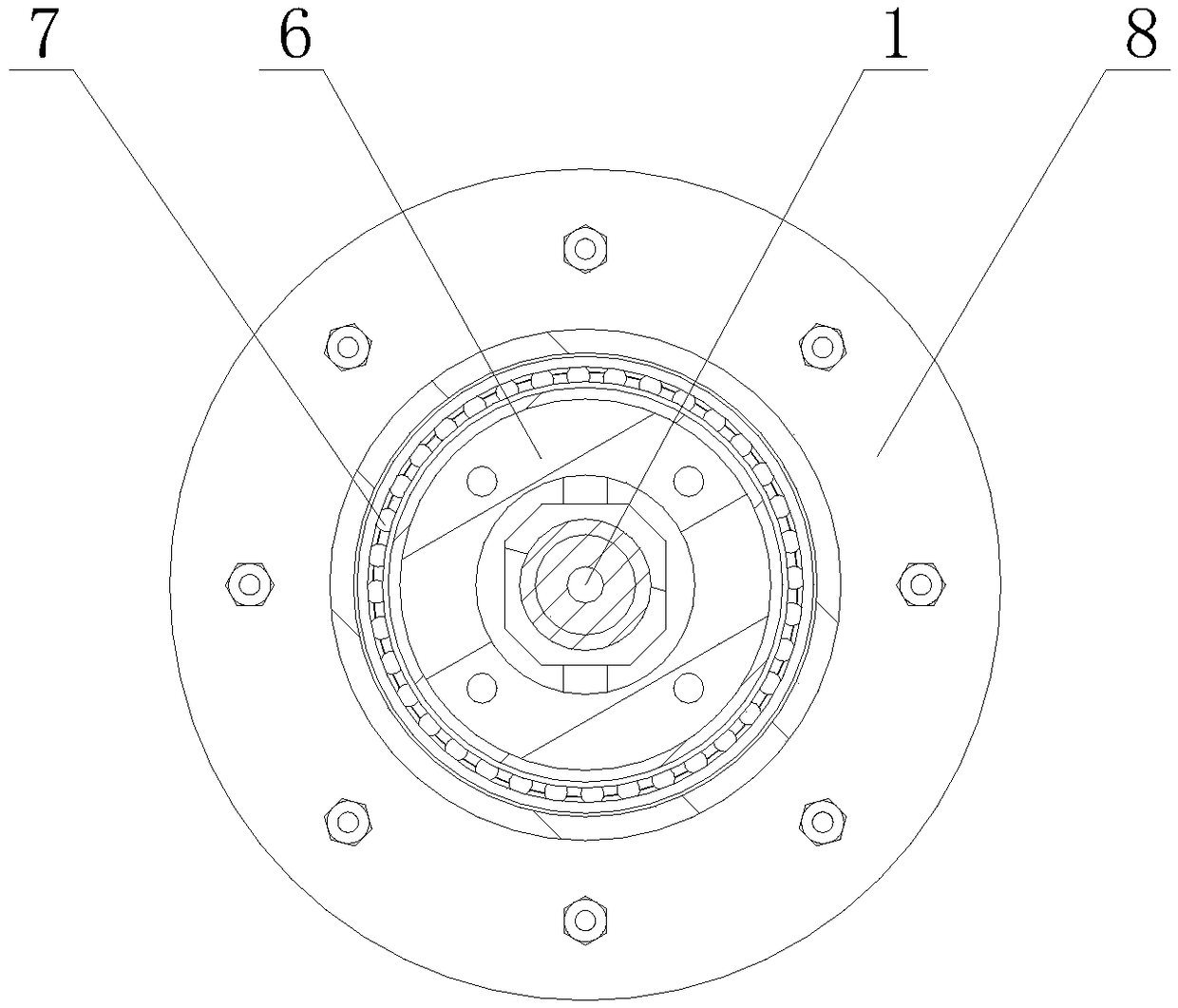
The invention discloses an in-process sintering machine trolley wheel automatic centering device, and belongs to the technical field of sintering engineering. The in-process sintering machine trolleywheel automatic centering device comprises a rotating shaft. A shaft end connector body is arranged at one end of the rotating shaft. A rotating connector is arranged on the other end of the rotatingshaft. A rotating shaft hanger is arranged outside the rotating shaft. A rotating sleeve is arranged at the outer ring of the rotating shaft in a sleeving mode. A bearing is arranged at the outer ringof the rotating shaft. Through guiding carried out by a on-wheel positioning block, sealing fit between the shaft end connector body at the front end of the rotating shaft and an on-wheel connector body located at a wheel, and superposition displacement by relative rotation between the rotating sleeve and a shell and relative slippage between a rotating shaft cantilever and the rotating sleeve, the freedom degree of the shaft end connector body at the front end of the rotating shaft can be guaranteed to adapt to direction deviation of the wheel, lubricating grease can be guaranteed to be filled in the wheel under pressure, and therefore the oil supply process is stable, source utilization rate is effectively improved, and good economic benefits can be produced.

Description

technical field [0001] The invention relates to the technical field of sintering engineering, and more specifically relates to an automatic centering device for a wheel of a sintering machine in motion. Background technique [0002] During the production process of the sintering machine, the sintering machine trolley needs to keep working continuously. The wheels of the sintering machine trolley work under high temperature conditions for a long time, the bearing grease is consumed rapidly, and the requirements for grease replenishment are high. Over the years, the wheel of the sintering machine trolley has been manually filled with grease when the sintering machine is stopped. During the limited downtime for maintenance, the wheels of the sintering machine trolley cannot be effectively lubricated. Moreover, the lubricating grease in the wheels of the sintering machine trolley has been consumed within the interval between sintering machine shutdowns. Insufficient lubricati...

Claims


Application Information

Patent Timeline
Patent Type & Authority Applications(China)
IPC IPC(8): F27B14/08
Inventor 杜预董岱卫卫石海军陈猛
Owner HUATIAN ENG & TECH CORP MCC
Learn More