Uniform-temperature heating furnace

A heating furnace and furnace body technology, applied in the field of uniform temperature heating furnace, can solve the problems of inability to ensure uniform combustion temperature of the furnace body, single heating direction, insufficient installation position, etc., achieve good application and promotion value, improve production efficiency, The effect of easy disassembly

Inactive Publication Date: 2018-11-16
湖北中冶窑炉有限公司
View PDF14 Cites 1 Cited by
  • Summary
  • Abstract
  • Description
  • Claims
  • Application Information

AI Technical Summary

Problems solved by technology

When the steel in the heating furnace is heated by the installation method on the furnace roof or side wall, there are problems such as single heating direction and small heating area.
At the same time, since the heating furnace is a customized equipment, it is necessary to make different design changes to the appearance and size of the heating furnace according to the customer's requirements during design. In some cases, the heating furnace designed and manufactured for the customer cannot When the burner is installed on the side wall and the burner is installed on the top (usually installed in the middle of the furnace top), and the furnace top has too many pipes, the installation position is not enough, and the temperature uniformity of the combustion inside the furnace body cannot be guaranteed.

Method used


Image

  • Uniform-temperature heating furnace
  • Uniform-temperature heating furnace

Examples


Embodiment Construction

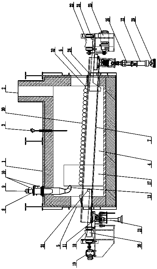
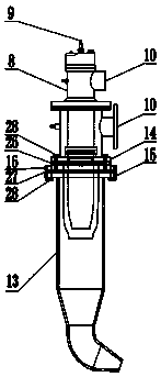
[0019] A kind of uniform temperature heating furnace of the present embodiment, see figure 1 , figure 2 , has a furnace body 1, a flue 2 is opened on the top of the furnace body 1, and a temperature detector 3 and a burner device are installed, a furnace body 4 is opened in the furnace body 1, and a feed port is respectively opened on the left and right sides of the furnace body 4 5 and the discharge port 6, a feed transmission mechanism is provided on the side of the feed port 4, a discharge transmission mechanism is provided on the side of the discharge port 6, a row of girders 7 are arranged side by side in the furnace 4, and there is a gap between two adjacent girders 7 There are gaps, the first and last ends of each girder 7 run through between the feed port 5 and the discharge port 6, the burner device has a burner body 8, and the burner body 8 is provided with a gas inlet 9 and an air inlet 10 , the head end of the girder 7 is set on the fixed shaft 11, the tail end o...


PUM


Abstract

The invention discloses a uniform-temperature heating furnace. The uniform-temperature heating furnace comprises a furnace body. A flue is formed on the top of the furnace body, and a temperature detector and a burner device are installed on the top of the furnace body. A combustion chamber is formed in the furnace body, and a feeding inlet and a discharging outlet are formed in the left side andthe right side of the combustion chamber correspondingly. A feeding transmission mechanism is arranged on the feeding inlet side, and a discharging transmission mechanism is arranged on the discharging outlet side. Girders are installed in the combustion chamber and penetrate through the space between the feeding inlet and the discharging outlet. The burner device comprises a burner body, and a fuel gas inlet and air inlets are formed in the burner body. The head ends of the girders are installed on a fixing shaft in a sleeved mode, and a hydraulic cylinder is installed at the tail ends of thegirders. A flame guide pipe is installed at the outlet end of the burner body in a sleeving mode, an installation plate is arranged on the outer wall of the burner body, an edge opening is formed ina pipe opening of the flame guide pipe and connected with the installation plate through a transfer plate, and the outlet end of the flame guide pipe is of a hook-shaped structure. The uniform-temperature heating furnace is simple in structure. Due to the fact that the flame guide pipe is installed on the existing burner body, disassembly is convenient, the heating direction of the burner body canbe changed at will, the heating area of the burner is increased, and the uniform-temperature heating furnace has the high application and promotional value.

Description

technical field [0001] The invention relates to the technical field of heat treatment equipment, in particular to a uniform temperature heating furnace. Background technique [0002] In the metallurgical industry, a heating furnace is a device that heats materials or workpieces to the temperature of rolling to forging. Heating furnaces are used in petroleum, chemical, metallurgy, machinery, heat treatment, surface treatment, building materials, electronics, materials, light industry, daily chemicals, pharmaceuticals and many other industries. [0003] At present, the burner devices commonly used in heating furnaces are divided into two types: top spray and side spray. steel is heated. When the steel in the heating furnace is heated by means of installation on the furnace roof or side wall, there are problems such as single heating direction and small heating area. At the same time, since the heating furnace is a customized equipment, it is necessary to make different desi...

Claims


Application Information

Patent Timeline
Patent Type & Authority Applications(China)
IPC IPC(8): F27B17/00F27D19/00C21D1/52C21D9/00
CPCF27B17/00F27D19/00C21D1/52C21D9/00F27D2019/0003
Inventor 樊利军黄振林王付宏
Owner 湖北中冶窑炉有限公司
Why Eureka
Try Eureka