

Dedicated device and method for detecting quality of Hall sensor
A Hall sensor and detection device technology, applied in the field of sensor detection, can solve the problems of high product detection cost, low production efficiency, long detection time, etc., and achieve good batch calibration consistency, no manual intervention error, and improve production efficiency. Effect
- Summary
- Abstract
- Description
- Claims
- Application Information
AI Technical Summary
Problems solved by technology
Method used
Image

Examples
Embodiment 1
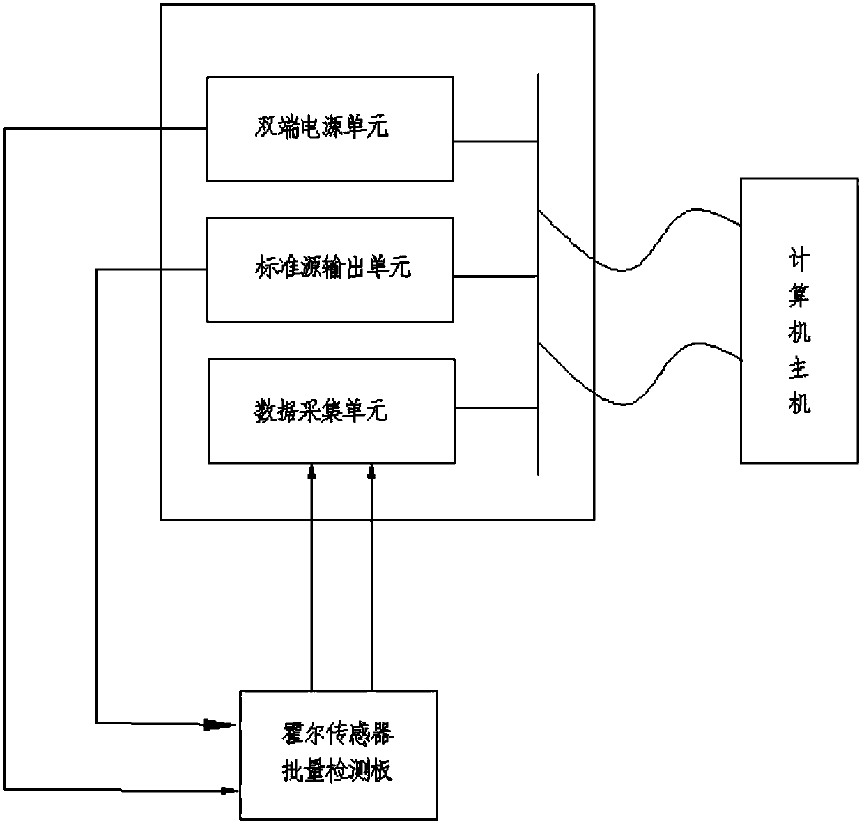
[0062] Such as figure 1 , 2 , 3 shown.
[0063] A special detection device for Hall sensor quality, including:
[0064] Hall sensor batch detection board, Hall sensor batch measurement device and computer for processing the detection data;
[0065] The Hall sensor batch detection board is used for parallel circuit connection to the batch Hall sensors;
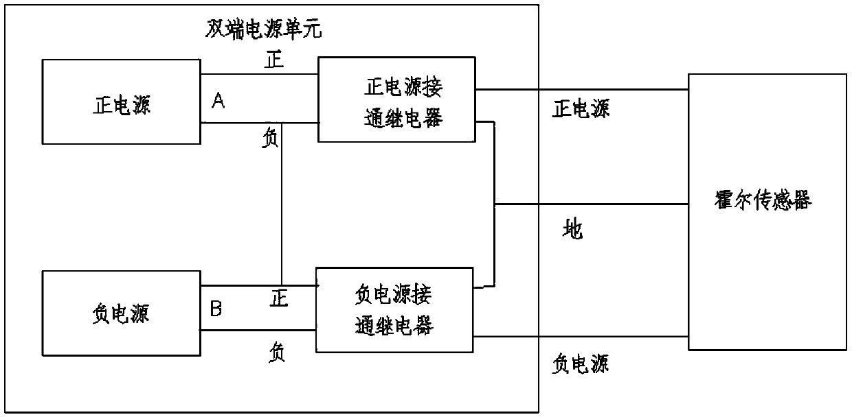
[0066] The Hall sensor batch measurement device includes integrated connection: a double-ended power supply unit, a standard source output unit and a data acquisition unit;
[0067] The double-terminal power supply unit is a positive and negative power supply that is powered on at the same time or at intervals; the standard source output unit provides a standard source output for the Hall sensor to be measured; The Hall sensor performs positive and negative power input and standard source input respectively, and then the data acquisition unit performs real-time acquisition respectively for the signal output of the Hall sens...
Embodiment 2
[0071] A method for detecting the quality of a Hall sensor using the detection device as described in Embodiment 1, the difference is that the method includes:
[0072] 1. Set the Hall sensor detection value:
[0073] Set the standard power supply voltage of the Hall sensor, the zero point error limit, the positive and negative stroke linear standard limit, and the positive and negative bias voltage limit; set the minimum value, maximum value, and stroke points of the Hall sensor, according to (maximum value-minimum value) / number of travel points+1 to automatically calculate the current set value of the travel point; for example, the minimum value is 0, the maximum value is 50A, and the travel point 10 is formed according to the calculation formula (50-0) / 10+1=11 The detection points are 0A, 1A, 2A, 3A, 4A, 5A, 6A, 7A, 8A, 9A, and 10A; the travel current of the Hall sensor above comes from the standard source module controlled by the computer, and the digital input set value a...
Embodiment 3
[0098] A method utilizing detection as described in Embodiment 2, the difference is that in step 2, the positive stroke of the Hall sensor is detected:
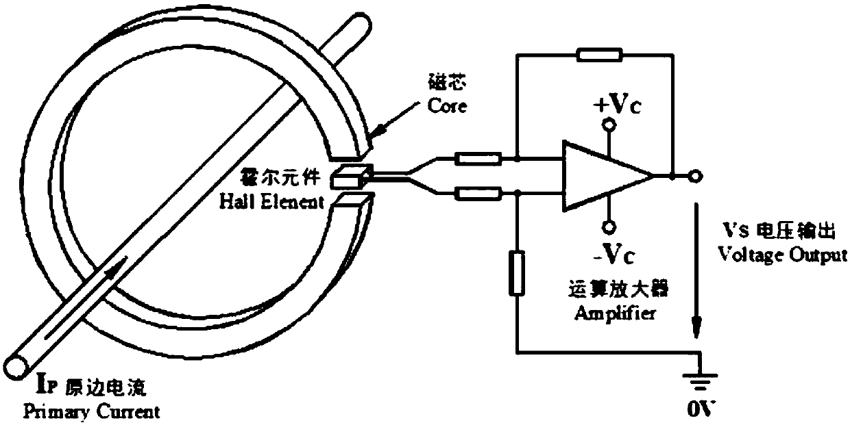
[0099] The computer controls the output of the double-terminal power supply unit to set the positive and negative voltages as the detected Hall sensor power supply +Vc and -Vc, and controls the standard source current Ip from the minimum value to the maximum value according to the control value of the travel node, and the current is stable at the travel point each time. When the control value is reached, start to collect the output voltage detection value Vs of the Hall sensor, and calculate the error, and then adjust the current at the next stroke point until the maximum current is reached and the detection is completed. Calculate the linear value and display whether it is less than the positive stroke linear standard limit : When it is greater than the positive stroke linear standard limit, it is determined that the quality ...
PUM
 Abstract
Description
Claims
Application Information