Single-sided circuit antenna plate with shockproof legs

An antenna board, single-sided technology, applied in the direction of the antenna support/installation device, etc., can solve the problems of being easily damaged, unable to buffer, and the antenna board does not have the effect of shock resistance, and achieves the effect of increasing performance, simple structure and convenient use.

Inactive Publication Date: 2018-11-16
扬州市玄裕电子有限公司
View PDF0 Cites 2 Cited by
  • Summary
  • Abstract
  • Description
  • Claims
  • Application Information

AI Technical Summary

Problems solved by technology

[0002] Nowadays, the technological progress of electronic technology is rapid, and various electronic products (such as satellite navigators, wireless TV monitors, etc.) are constantly being introduced. The electronic products not only have more and more functions, but also can give people a lot of convenience The price is also getting lower and lower. Therefore, nowadays, people of all ages and sexes use various electronic products more commonly than in the past. However, with the economic turmoil in recent years, people’s job opportunities and income have dropped significantly, making People no longer only pay attention to the functionality of various electronic products, but pay more attention to the durability of various electronic products. Therefore, in order to meet the needs of many consumers nowadays, various electronic product manufacturers are all committed to research and development. Electronic products that are advanced and have a longer service life to meet consumer demand trends, thereby enhancing the competitiveness of electronic products in the market, and as the requirements for electronic products become higher and higher, structural antenna boards in electronic products The requirements are also getting higher and higher, and the traditional antenna board does not have the effect of shock resistance. When it receives external pressure, it cannot buffer and is easily damaged. Therefore, we propose a single-sided line antenna with shock-proof feet plate

Method used


Image

  • Single-sided circuit antenna plate with shockproof legs
  • Single-sided circuit antenna plate with shockproof legs

Examples


Embodiment Construction

[0014] The following will clearly and completely describe the technical solutions in the embodiments of the present invention with reference to the accompanying drawings in the embodiments of the present invention. Obviously, the described embodiments are only some, not all, embodiments of the present invention. Based on the embodiments of the present invention, all other embodiments obtained by persons of ordinary skill in the art without making creative efforts belong to the protection scope of the present invention.

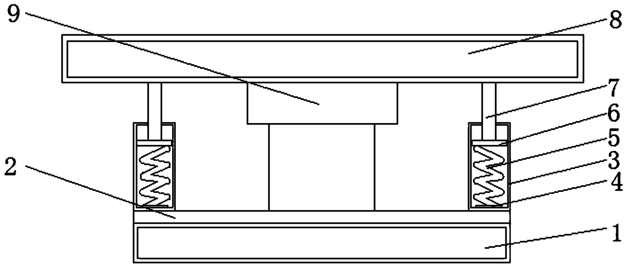
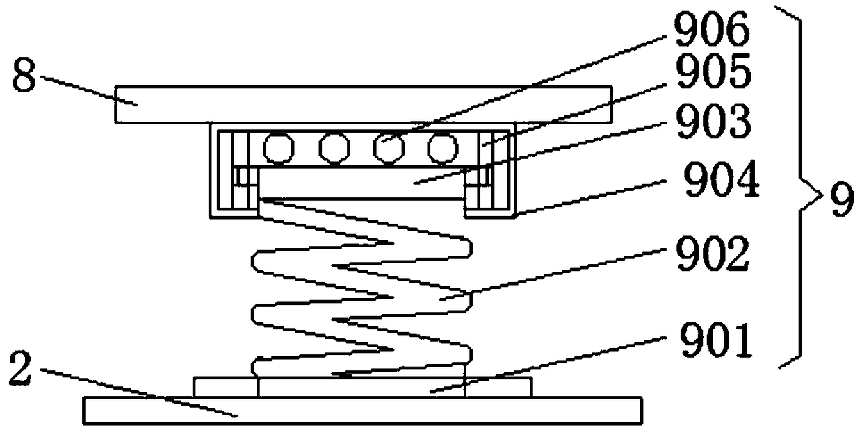
[0015] see Figure 1-2 , the present invention provides a technical solution: a single-sided line antenna board with shockproof feet, including a base plate 1, a cushion pad 2 is provided on the top of the base plate 1, and sleeves 3 are provided on the left and right sides of the top of the cushion pad 2 The bottom of the inner cavity of the two groups of sleeves 3 is provided with a welding block 4, the top of the welding block 4 is provided with a spring 5,...


PUM


Abstract

The invention discloses a single-sided circuit antenna plate with shockproof legs in the technical field of antenna plates. A main cushion post comprises a lower fixed part, and the bottom of the lower fixed part is connected with a cushion pad; a cushion spring is arranged on the top of the lower fixed part; a cushion block is arranged between the top of an upper fixed part and the top of the inner cavity of a cushion loop bar; the top of the cushion loop bar is connected with the bottom center of the antenna plate; the left and right sides of the top of a base plate are connected with the antenna plate through cushion sleeves; the inner cavities of the cushion sleeves are used for cushioning stress through the spring and the loop bar, so that the pressure received by the left and right sides of the antenna plate can be cushioned; the main cushion post is arranged at the central position between the base plate and the antenna plate; the main cushion post is used for cushioning the pressure suffered by the antenna plate through the cushion spring and the cushion loop bar; and the cushion block is arranged at the joint of the top of the cushion spring and the inner cavity of the cushion loop bar, so that the performance of shockproof cushioning is increased.

Description

technical field [0001] The invention relates to the technical field of antenna boards, in particular to a single-sided line antenna board with anti-vibration feet. Background technique [0002] Nowadays, the technological progress of electronic technology is rapid, and various electronic products (such as satellite navigators, wireless TV monitors, etc.) are constantly being introduced. The electronic products not only have more and more functions, but also can give people a lot of convenience The price is also getting lower and lower. Therefore, nowadays, people of all ages and sexes use various electronic products more commonly than in the past. However, with the economic turmoil in recent years, people’s job opportunities and income have dropped significantly, making People no longer only pay attention to the functionality of various electronic products, but pay more attention to the durability of various electronic products. Therefore, in order to meet the needs of many ...

Claims


Application Information

Patent Timeline
Patent Type & Authority Applications(China)
IPC IPC(8): H01Q1/12
CPCH01Q1/12
Inventor 单金林姜文军段小篇郝晓锋
Owner 扬州市玄裕电子有限公司
Why Eureka
Try Eureka