Control method and device for automatic emergency braking system

A technology of automatic emergency braking and control methods, which is applied in the directions of control devices, transportation and packaging, and input parameters of external conditions, and can solve problems such as acceleration and braking switching mechanisms that are not considered, and achieve the effects of avoiding collisions and reducing collision damage

Active Publication Date: 2018-11-20
JIANGXI RONGCHENG MACHINERY MFG CO LTD
View PDF7 Cites 27 Cited by
  • Summary
  • Abstract
  • Description
  • Claims
  • Application Information

AI Technical Summary

Problems solved by technology

This approach does not take into account the mechanism of switching between acceleration and braking, and how to deal with situations where the risk of collision may also arise when the driver is actively braking

Method used


Image

  • Control method and device for automatic emergency braking system
  • Control method and device for automatic emergency braking system

Examples


Embodiment 1

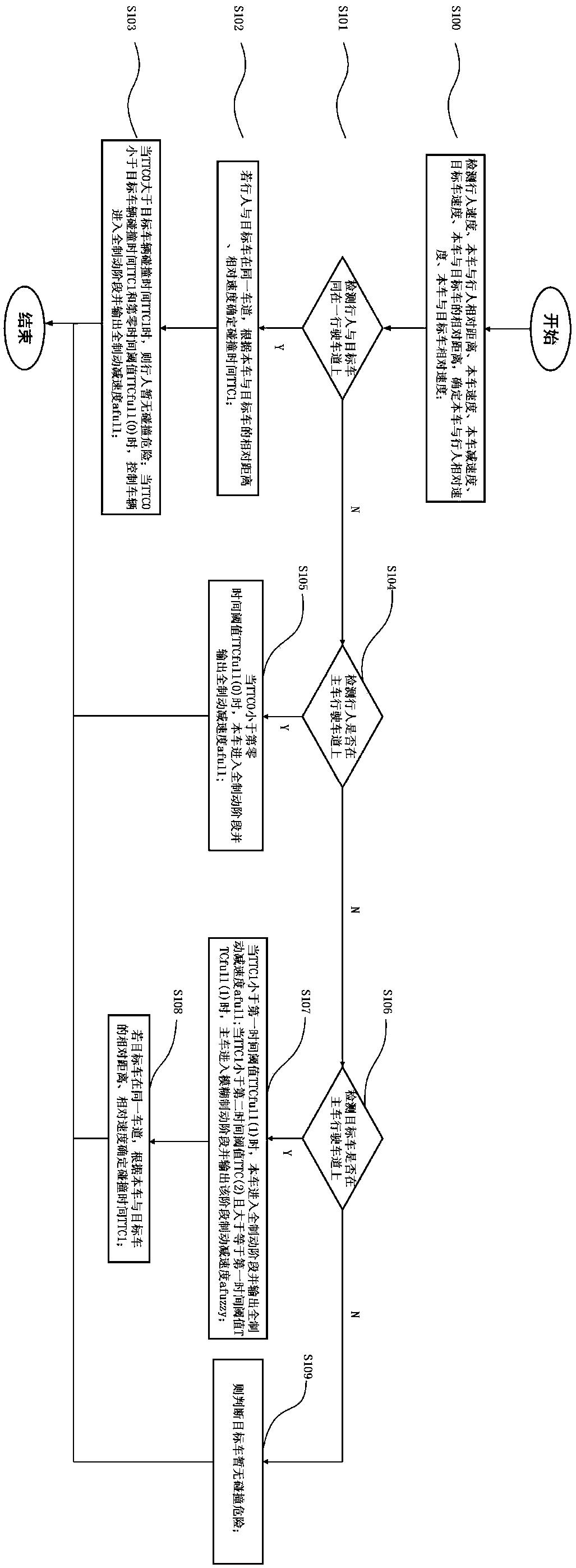
[0041] Such as figure 1 As shown, it is a flow chart of the steps of an automatic emergency braking system control method in an embodiment of the present invention, and the control method includes:

[0042] Step S100, detecting the speed of the pedestrian, the relative distance between the vehicle and the pedestrian, the speed of the vehicle, the deceleration of the vehicle, the speed of the target vehicle, the relative distance between the vehicle and the target vehicle, and determining the relative speed between the vehicle and the pedestrian and the relative speed between the vehicle and the target vehicle speed.

[0043] In a specific embodiment, the relative distance and relative speed are obtained through millimeter-wave radar, the speed of the vehicle and the braking deceleration of the driver of the vehicle are obtained through the CAN message of the vehicle, and the braking execution module based on the deceleration is the bottom vehicle control device.

[0044] Ste...

Embodiment 2

[0064] Such as figure 2 As shown, it is a structural diagram of an automatic emergency braking system control device in an embodiment of the present invention, referring to figure 2 As shown, the device includes: a perception detection module 201, which is used to detect the speed of pedestrians, the relative distance between the vehicle and pedestrians, the speed of the vehicle, the deceleration of the vehicle, the speed of the target vehicle, the relative distance between the vehicle and the target vehicle, and determine the distance between the vehicle and the target vehicle. Relative speed with pedestrians, relative speed between the car and the target car, and whether the pedestrian, the target car, and the pedestrian and the target car are on the lane; the calculation and decision-making module 202 is connected with the perception detection module, and is used for determining the distance between the car and the pedestrian or target The relative distance and relative s...


PUM


Abstract

The invention relates to a control method and device for an automatic emergency braking system, and belongs to the technical field of vehicle braking system. The method comprises the steps that whether or not a pedestrian and a target vehicle are on a driveway of a host vehicle, the speed of the pedestrian, the relative distance between the host vehicle and the pedestrian, the speed of the host vehicle, deceleration of the host vehicle, the speed of the target vehicle and the relative distance between the host vehicle and the target vehicle are detected, and the relative speed of the host vehicle and the pedestrian and the relative speed of the host vehicle and the target vehicle are determined. According to the method and the device, the pedestrian and the target vehicle can be distinguished, according to the host vehicle and target objects including the state of a driver, emergency circumstances are comprehensively and accurately judged, and braking is conducted; fuzzy braking for simulating manned driving can be achieved, and then effective and stable collision avoidance or collision damage lowering is achieved.

Description

technical field [0001] The invention relates to an automatic emergency braking system control method and device, and belongs to the technical field of automobile braking systems. Background technique [0002] With the increase in the number of cars and the increasingly complex traffic environment and other factors, more and more attention has been paid to social focus issues such as traffic safety. For this reason, automobile manufacturers, spare parts manufacturers and scientific research institutions have carried out a lot of research on automobile safety technology. Among them, the Automatic Emergency Braking (AEB) system has been widely used in the assisted driving system of automobiles, and has gradually become an essential subsystem of the automobile safety guarantee system. It can issue an alarm and implement braking intervention before a car collision occurs, so as to avoid accidents and minimize the impact of accidents. The AEB system has the characteristics of si...

Claims


Application Information

Patent Timeline
Patent Type & Authority Applications(China)
IPC IPC(8): B60W30/09B60W30/095B60W50/00B60W50/14
CPCB60W30/09B60W30/095B60W50/00B60W50/14B60W2050/0001B60W2050/143B60W2554/80B60W2554/801B60W2555/00
Inventor 李骏钟陈志鹏邓海龙唐俊涛
Owner JIANGXI RONGCHENG MACHINERY MFG CO LTD
Why Eureka
Try Eureka