Conveyor for mechanically packaging plastic plate and strip

A plastic plate and belt conveying technology, applied in the direction of conveyors, conveyor objects, transportation and packaging, etc., can solve the problems of increasing weight, increasing the length of the drive shaft, increasing costs, etc., to meet functional requirements, reduce size, and solve The effect of space tension

Pending Publication Date: 2018-11-20
MIRACLE AUTOMATION ENG CO LTD
View PDF10 Cites 0 Cited by
  • Summary
  • Abstract
  • Description
  • Claims
  • Application Information

AI Technical Summary

Problems solved by technology

[0003] Since each station on the plastic slab conveyor has a skid carrying workpieces, an operator and a tool trolley, the entire conveyor is required to have a large width, which will result in an increase in the length of the entire drive shaft, and the shaft becomes larger in size
The length of the drive shaft is too long and it is difficult to process and heat treat. The increase in the size of the shaft not only greatly increases its own weight, but also the too compact space does not allow the size of the shaft to increase a lot
When the whole line itself is very long, the cumulative error of the length of the conveyor belt itself and the total elongation after a period of use will be greater, which will cause the lower return plastic conveyor belt to be too long and directly contact the ground, resulting in plastic Conveyor belt wear
[0004] At the same time, the plastic slab conveyor in the prior art is located in the pit from the beginning to the end. Many factors need to be considered in digging the pit in the factory building, which is time-consuming and laborious, and has certain precision requirements, otherwise it will seriously affect the equipment installation
Due to the large overall load of the entire conveyor, according to the existing structure, it is necessary to select a very large high-power motor reducer, which not only leads to an increase in cost, but also requires a large space for the motor reducer with an oversized shape

Method used


Image

  • Conveyor for mechanically packaging plastic plate and strip
  • Conveyor for mechanically packaging plastic plate and strip
  • Conveyor for mechanically packaging plastic plate and strip

Examples


Embodiment Construction

[0032] The present invention will be further described below in combination with specific embodiments and accompanying drawings.

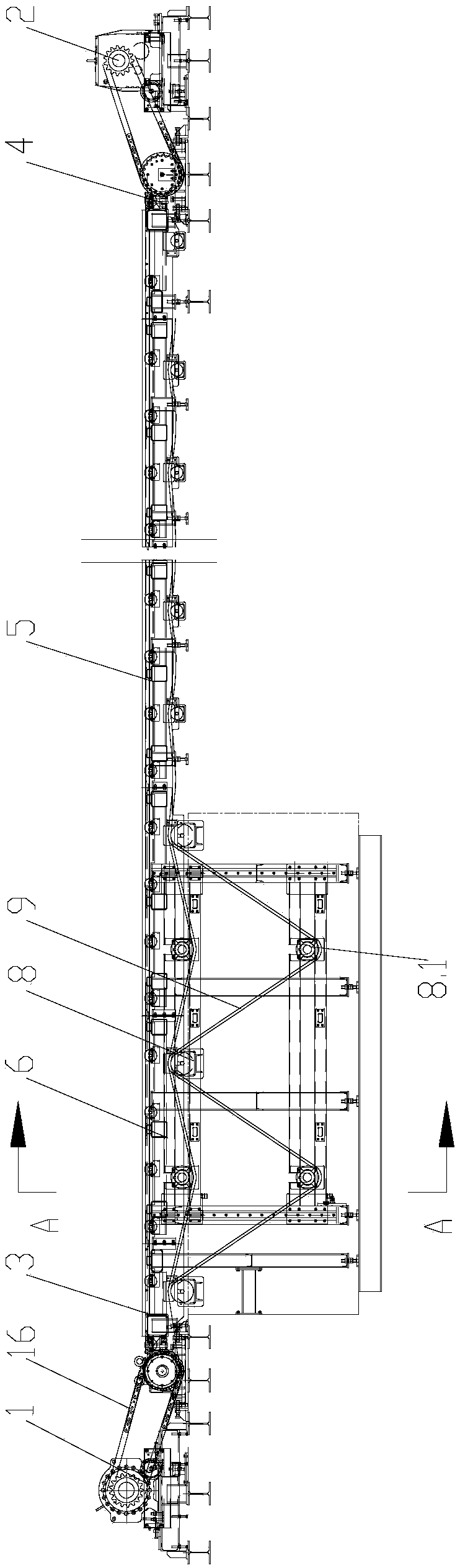
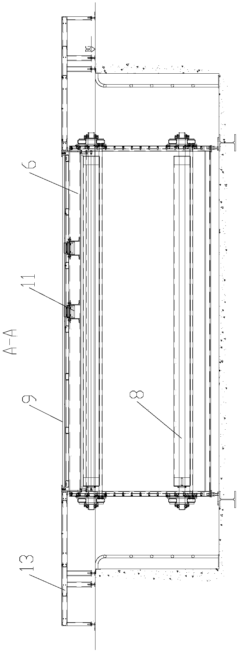
[0033] Such as figure 1 Shown: a mechanical subpackage plastic plate belt conveyor, including a drive assembly, a frame assembly and a plastic conveyor belt 9, and steps 13 are provided on both sides of the frame assembly. Wherein, the drive assembly includes a main drive assembly 1 and an auxiliary drive assembly 2, and the frame assembly includes a main drive frame assembly 3, two non-standard frame assemblies 6, multiple standard frame assemblies 5 and auxiliary drive frame assemblies 4 fixedly connected in sequence.

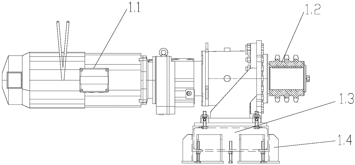
[0034] Such as image 3 Shown: the main drive assembly 1 includes a motor reducer 1.1, a main drive sprocket 1.2 and a motor base 1.3, the motor reducer 1 is installed on the motor base 1.3, and the main drive sprocket 1.2 is installed on the output shaft of the motor reducer 1.1. In order to ensure the stability of the structur...


PUM


Abstract

The invention relates to a conveyor, in particular to a conveyor for mechanically packaging plastic plates and strips. The conveyor comprises a main driving assembly, a main driving frame assembly, two nonstandard frame assemblies, a plurality of standard frame assemblies, a secondary driving frame assembly and a secondary driving assembly, wherein the main driving assembly, the main driving frameassembly, the two nonstandard frame assemblies, the plurality of standard frame assemblies, the secondary driving frame assembly and the secondary driving assembly are arranged in sequence. The conveyor has the beneficial effects that the problem of wear of a plastic conveying belt is effectively solved; the size of a driving shaft is greatly reduced, the functional requirement is satisfied, andthe problem of limited space and the problem of shaft processing are solved; the power of a motor reducing gear is reduced, and the cost and space are reduced; and a counterweight assembly which is used for performing gravity tensioning on the conveying belt is located in a pit, and other parts are integrally installed on the ground, so that the overhaul and installation are convenient, the previous large-scale pit excavation is omitted, and time and labor are saved.

Description

technical field [0001] The invention relates to a conveyor, in particular to a conveyor for mechanically packing plastic plate belts. Background technique [0002] The function of the mechanical packing plastic plate belt conveyor is: while conveying the sled carrying workpieces, the operator is located on both sides of the sled to assemble the workpieces on the sled. There are more than 20 operating stations on the plastic sheet belt, and each station has a skid with workpieces, two operators, and a tool cart. [0003] Since each station on the plastic slab conveyor has a skid carrying workpieces, an operator and a tool trolley, the entire conveyor is required to have a large width, which will result in an increase in the length of the entire drive shaft, and the shaft size becomes larger. The length of the drive shaft is too long to be processed and heat treated. The increase in the size of the shaft not only greatly increases its own weight, but also the too compact spa...

Claims


Application Information

Patent Timeline
Patent Type & Authority Applications(China)
IPC IPC(8): B65G23/44B65G23/24B65G39/12
CPCB65G23/24B65G23/44B65G39/12
Inventor 瞿亮亮张华兵
Owner MIRACLE AUTOMATION ENG CO LTD
Why Eureka
Try Eureka