Paperboard turnover device

A technology of turning device and cardboard, which is applied in the direction of turning objects, transportation and packaging, pile separation, etc., can solve the problems of needing manual adjustment and unable to change the direction of cardboard, and achieves the effect of reducing manual input, fast turning and high work efficiency.

Pending Publication Date: 2018-11-20
广西北流盛丰源纸品有限公司
View PDF1 Cites 2 Cited by
  • Summary
  • Abstract
  • Description
  • Claims
  • Application Information

AI Technical Summary

Problems solved by technology

[0003] In order to solve the above-mentioned technical problems, the present invention provides a cardboard turning device, which can solve the problem that manual adjustment is required and the orientation of the cardboard cannot be changed in the prior art

Method used


Image

  • Paperboard turnover device
  • Paperboard turnover device
  • Paperboard turnover device

Examples


Embodiment Construction

[0020] The technical solution of the present invention is further described below, but the scope of protection is not limited to the description.

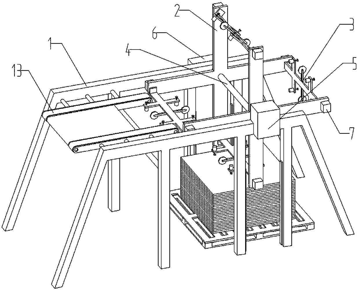
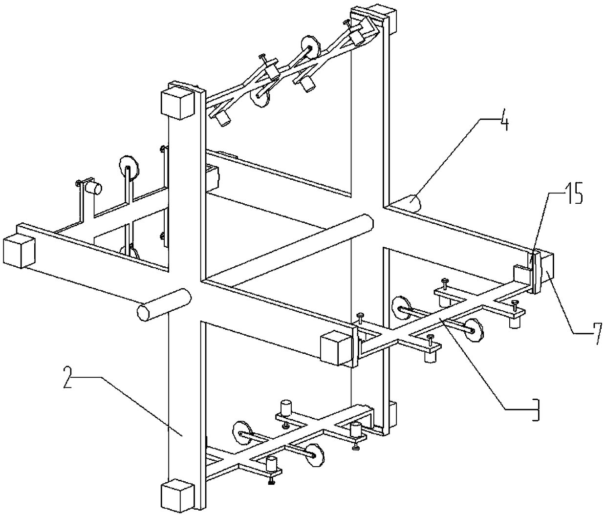
[0021] like figure 1 , figure 2 As shown, a cardboard turning device includes a frame 1, a rotating frame 2, and a turning frame 3. The rotating frame 2 is installed on the frame 1 through a rotating shaft 4. The rotating frame 2 is cross-shaped, and the turning frame 3 has a total of Four, installed on the end of the rotating frame 2 respectively, the rotating shaft 4 is a hollow shaft, one end of the rotating shaft 4 is connected to the motor A5, and the other end is connected to the pneumatic rotary joint 6, and the positive pressure interface is provided on the pneumatic rotary joint 6 and a negative pressure interface, the end of the rotating frame 2 is provided with a motor B7, and the output shaft of the motor B7 is connected with the turning frame 3.

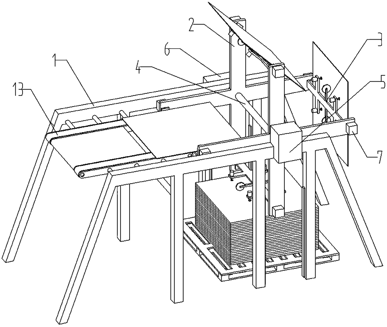
[0022] like image 3 As shown, when working, the motor A5 drives the...


PUM


Abstract

The invention discloses a paperboard turnover device. The paperboard turnover device comprises a rack, a rotary frame and four turnover frames. The rotary frame is mounted on the rack through a rotaryshaft. The rotary frame is in a crossed shape. The four turnover frames are mounted at the ends of the rotary frame correspondingly. The rotary shaft is a hollow shaft. One end of the rotary shaft isconnected with a motor A, and the other end of the rotary shaft is connected with a pneumatic rotary connector. The pneumatic rotary connector is provided with a positive-pressure port and a negative-pressure port. Motors B are arranged at the ends of the rotary frame. Output shafts of the motors B are connected with the turnover frames. The paperboard turnover device drives the turnover frames to rotate through the rotary frame. The turnover frames suck a paperboard through suction cups. When the rotary frame rotates, the direction of the paperboard is adjusted through the motors B to implement fast turnover of the paperboard, and the working efficiency is high. Moreover, the paperboard is rotated and placed on a conveyor belt. The placement accuracy is high. Manual adjustment is not needed. The labor input is reduced, and the reliability of the paperboard turnover device is improved.

Description

technical field [0001] The invention belongs to the field of carton production equipment, in particular to a cardboard turning device. Background technique [0002] At present, the commonly used cartons are all made of cardboard after printing, slotting, die-cutting, binding and other processes. In the printing and die-cutting process, large pieces of cardboard are usually processed by manual feeding The cardboard is placed on the conveyor belt of the processing equipment, which has a low degree of automation and low work efficiency. At the same time, for some large-scale cardboard, workers can only grasp the edge of the cardboard, and the cardboard is easily deformed during feeding, which affects product quality. To solve this problem, People have developed an automatic cardboard feeding machine, such as the Chinese patent application number 201710266109.3, which discloses a cardboard automatic feeding machine, which is characterized in that, along the cardboard conveying d...

Claims


Application Information

Patent Timeline
Patent Type & Authority Applications(China)
IPC IPC(8): B65H15/00
CPCB65H15/00B65H2701/176
Inventor 黄伟红林世豪李端武徐赣平
Owner 广西北流盛丰源纸品有限公司
Why Eureka
Try Eureka