
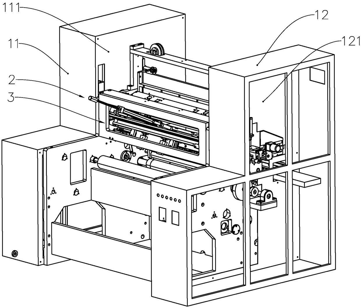
Reelpipe feeding device and paper reeling machine

A technology of rolling paper and driving device, which is applied in the direction of winding strips, transportation and packaging, thin material handling, etc. performance, avoid dislocation or drive dislocation, and improve the stability of the top tube

Pending Publication Date: 2018-11-20
ZHUHAI ZHONGYA PACKAGE EQUIP
View PDF0 Cites 1 Cited by
  • Summary
  • Abstract
  • Description
  • Claims
  • Application Information

AI Technical Summary

Problems solved by technology

[0002] Printing paper rolls generally consist of a coil tube in the center and paper wound around the coil tube. For small ticket print paper rolls, multiple coil tubes are arranged in the axial direction when rolling paper, and a larger The paper is wound on multiple roll tubes at the same time, and finally divided by a cutter. This involves the feeding method of the roll tube. The existing feeding method is to push the roll tube to the carrier through the push rod, and then the The feeding of the carrier frame transports the roll tube to the roll paper position. When the roll tube is loaded, the first roll tube to be fed last needs to be separated from the second roll tube to be fed. However, when feeding, Often the first roll tube will drive the second roll tube to move, resulting in misalignment of feeding, or dislocation of the next feeding position, seriously affecting the stability of the winding machine

Method used


Image

  • Reelpipe feeding device and paper reeling machine
  • Reelpipe feeding device and paper reeling machine
  • Reelpipe feeding device and paper reeling machine

Examples


no. 2 example

[0052] refer to Figure 14 , in the case of the above-mentioned embodiment, the present embodiment adds a sleeve 65, and the ejector rod of the ejector rod assembly 6 is sequentially sleeved with a first bearing 62, a sleeve 65, a plurality of second bearings 63 and end rods from the inside to the outside. Cover 64. The pipe sleeve 65 is sleeved on the end of the rod body 61, the pipe sleeve 65 is located between the first bearing 62 and the second bearing 63, the outer diameter of the pipe sleeve 65 is smaller than the outer diameter of the second bearing 63, and the axial length of the pipe sleeve 65 greater than the axial length of the second bearing 63 .

[0053] It can be seen from the above that the coiled tubes are pushed from the feeding rack to the carrier in a row, and after being pushed to a preset length, the carrier is driven to move along the direction of the coiled tube through the load-bearing drive assembly, and the distance between the carrier frame and the ...


PUM


Abstract

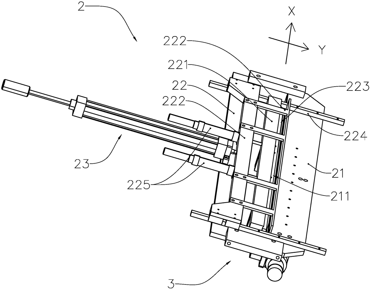
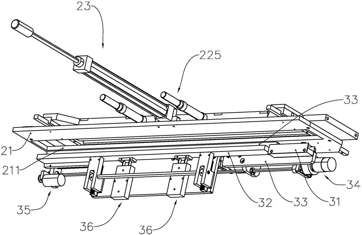
The invention provides a reelpipe feeding device and a paper reeling machine. The reelpipe feeding device comprises a bracket, a bearing rack, a feeding rack and a bearing driving assembly. The bearing rack is movably arranged on the bracket for bearing reelpipes, the bearing rack is arranged in an extended manner along the reelpipe placing direction; the feeding rack is fixedly arranged on the bracket for bearing the reelpipes; the feeding rack is located on the end part of the bearing rack in the reelpipe placing direction; the bearing driving assembly is connected to the bearing rack; the bearing driving assembly drives the bearing rack to move along the reelpipe placing direction; and a separation gap exists between the bearing rack and the feeding rack. The reelpipes in row are pushedto the bearing rack from the feeding rack and after the reelpipes are pushed to a preset length, the bearing rack is driven by the bearing driving assembly to move along the reelpipe placing direction and the separation gap exists between the bearing rack and the feeding rack, that is, the reelpipes are separated by means of transverse movement, and fed pipes and to-be-fed pipe are separated further, so that dislocation or driven dislocation is avoided, and the reelpipe feeding stability is improved effectively.

Description

technical field [0001] The invention relates to the field of paper rolling equipment, in particular to an upper pipe device and a paper rolling machine. Background technique [0002] Printing paper rolls generally consist of a coil tube in the center and paper wound around the coil tube. For small ticket print paper rolls, multiple coil tubes are arranged in the axial direction when rolling paper, and a larger The paper is wound on multiple roll tubes at the same time, and finally divided by a cutter. This involves the feeding method of the roll tube. The existing feeding method is to push the roll tube to the carrier through the push rod, and then the The feeding of the carrier frame transports the coiled tube to the paper roll position. When the coiled tube is loaded, the first coiled tube that is fed last and the second coiled tube to be fed need to be separated. However, when feeding, Often the first roll tube will drive the second roll tube to move, resulting in the di...

Claims


Application Information

Patent Timeline
Patent Type & Authority Applications(China)
IPC IPC(8): B65H19/30B65H18/02
CPCB65H18/028B65H19/30B65H2301/417B65H2701/1133
Inventor 王良忠王红星
Owner ZHUHAI ZHONGYA PACKAGE EQUIP
Learn More