Textile machine bracket

A textile machine and suction fan technology, applied in the direction of textile, loom, textile and paper making, etc., can solve the problems of accelerating internal parts, reducing the service life of equipment, and easily generating a large amount of heat, so as to avoid damage to parts and prolong the use Lifespan, effect of avoiding replacement

Inactive Publication Date: 2018-11-20
李亚丽
View PDF7 Cites 3 Cited by
  • Summary
  • Abstract
  • Description
  • Claims
  • Application Information

AI Technical Summary

Problems solved by technology

[0005] The purpose of the present invention is to solve the shortcomings in the prior art, such as: the frame of the existing textile machine has a single function, and the textile machine is easy to cause damage to the ground due to the large vibration when it is working, and some will cause the textile machine to Its own parts are damaged, and it is a waste of time to replace them, which seriously affects the production efficiency of the textile machine. At the same time, the textile machine is prone to generate a lot of heat when it is working, which accelerates the aging of internal parts and reduces the service life of the equipment.

Method used


Image

  • Textile machine bracket
  • Textile machine bracket
  • Textile machine bracket

Examples


Embodiment Construction

[0023] The following will clearly and completely describe the technical solutions in the embodiments of the present invention with reference to the accompanying drawings in the embodiments of the present invention. Obviously, the described embodiments are only some, not all, embodiments of the present invention.

[0024] In describing the present invention, it should be understood that the terms "upper", "lower", "front", "rear", "left", "right", "top", "bottom", "inner", " The orientation or positional relationship indicated by "outside", etc. is based on the orientation or positional relationship shown in the drawings, and is only for the convenience of describing the present invention and simplifying the description, rather than indicating or implying that the referred device or element must have a specific orientation, so as to Specific orientation configurations and operations, therefore, are not to be construed as limitations on the invention.

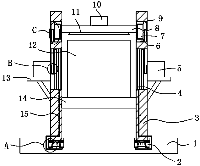
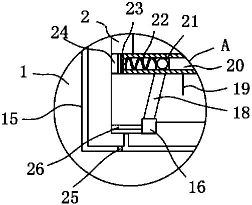
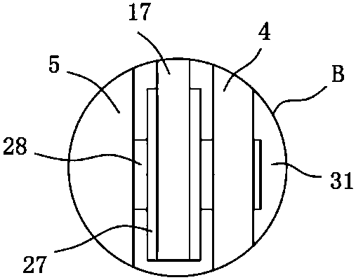
[0025] refer to Figure ...


PUM


Abstract

The invention discloses a textile machine bracket. The textile machine bracket comprises a base, wherein the base is connected with two vertical plates through a buffer device, a bearing plate is fixedly connected between the two vertical plates, a textile machine body is arranged on the bearing plate, a mounting plate is also arranged between the two vertical plates, the mounting plate is locatedabove the bearing plate, each vertical plate is provided with a heat dissipation device and a power generation device, and the mounting plate is further provided with a velvet suction device. The textile machine bracket has the advantages that mechanical energy is converted into internal energy of water, the vibration is reduced, the damage of parts is avoided while frequent replacement is avoided, the production efficiency of a textile machine is increased, wind power is generated so as to form air convection, so that temperature exchange of the air is achieved, water in a sponge pad absorbsheat through volatilization, so that the temperature is further lowered, a heat dissipation function is achieved, internal parts are prevented from aging, and the service life of equipment is prolonged.

Description

technical field [0001] The invention relates to the technical field of textile machines, in particular to a textile machine support. Background technique [0002] Textile machine is exactly the full name of the tool that processes thread, silk, hemp and other raw materials into silk thread and then weaves it into cloth. Such as spinning pendants, spinning wheels, spindles, pedal looms, as well as modern mechanical looms, modern numerical control automatic looms, etc., and the textile frame is a foundation of the textile machine, and the quality of the textile frame determines a The performance of the textile machine. [0003] The application number is CN 206692826 U, which discloses a textile machine support that is easy to move, including a working panel and a fixed panel, the fixed panel is located at the bottom of the working panel, and shock-absorbing A motor is provided in the middle of the bottom of the fixed panel, and a rotating shaft is provided at the output end ...

Claims


Application Information

Patent Timeline
Patent Type & Authority Applications(China)
IPC IPC(8): D03D49/02D03J1/00
Inventor 李亚丽
Owner 李亚丽
Why Eureka
Try Eureka