Cartridge balance valve

A balance valve and plug-in technology, which is applied in the direction of fluid pressure actuators, servo motor components, mechanical equipment, etc., can solve the problems of untimely buffering of balance valves, hazards of hydraulic devices, and influence on the safety and reliability of the whole machine.

Pending Publication Date: 2018-11-20
佛山信卓派思机械科技有限公司
View PDF1 Cites 4 Cited by
  • Summary
  • Abstract
  • Description
  • Claims
  • Application Information

AI Technical Summary

Problems solved by technology

[0003] The existing hydraulic balance valve generally has such a shortcoming: when the load is lowered, due to the characteristics of sudden changes in the flow area of ​​the valve port of the hydraulic balance valve, it will cause low-frequency jitter and impact on the load, resulting in system instability and affecting the overall performance. The safety and reliability of the machine; and during the working process of the oil cylinder, because the balance valve cannot buffer the pressure peak generated by the load impact in time, it also causes great harm to the hydraulic device.
In actual application, because the valve core has many matching components, and the tail is equipped with a sealing ring, the overall friction force is large, and the opening of the valve core has a certain delay, which causes the actual peak pressure in the system to be greater than the set pressure of the spring.
For example, the maximum pressure set by the spring is 20MPa. In practical applications, due to the delayed opening of the valve core, the peak pressure can reach 35-40MPa, which will cause certain harm to the safety of the hydraulic device.
[0006] (3) When the load rises, falls, and safety overflow passes through the same valve port, that is, the valve core and valve seat forming this valve port must be opened and closed once each time it rises, falls, and safety overflows. In this case, the frequency of use of the valve core or valve seat is high, which shortens the service life

Method used


Image

  • Cartridge balance valve
  • Cartridge balance valve
  • Cartridge balance valve

Examples


Embodiment Construction

[0026] Embodiments of the present invention are described in detail below, examples of which are shown in the drawings, wherein the same or similar reference numerals designate the same or similar elements or elements having the same or similar functions throughout. The embodiments described below by referring to the figures are exemplary and are intended to explain the present invention and should not be construed as limiting the present invention.

[0027] The cartridge type balance valve according to the embodiment of the present invention will be described in detail below with reference to the accompanying drawings.

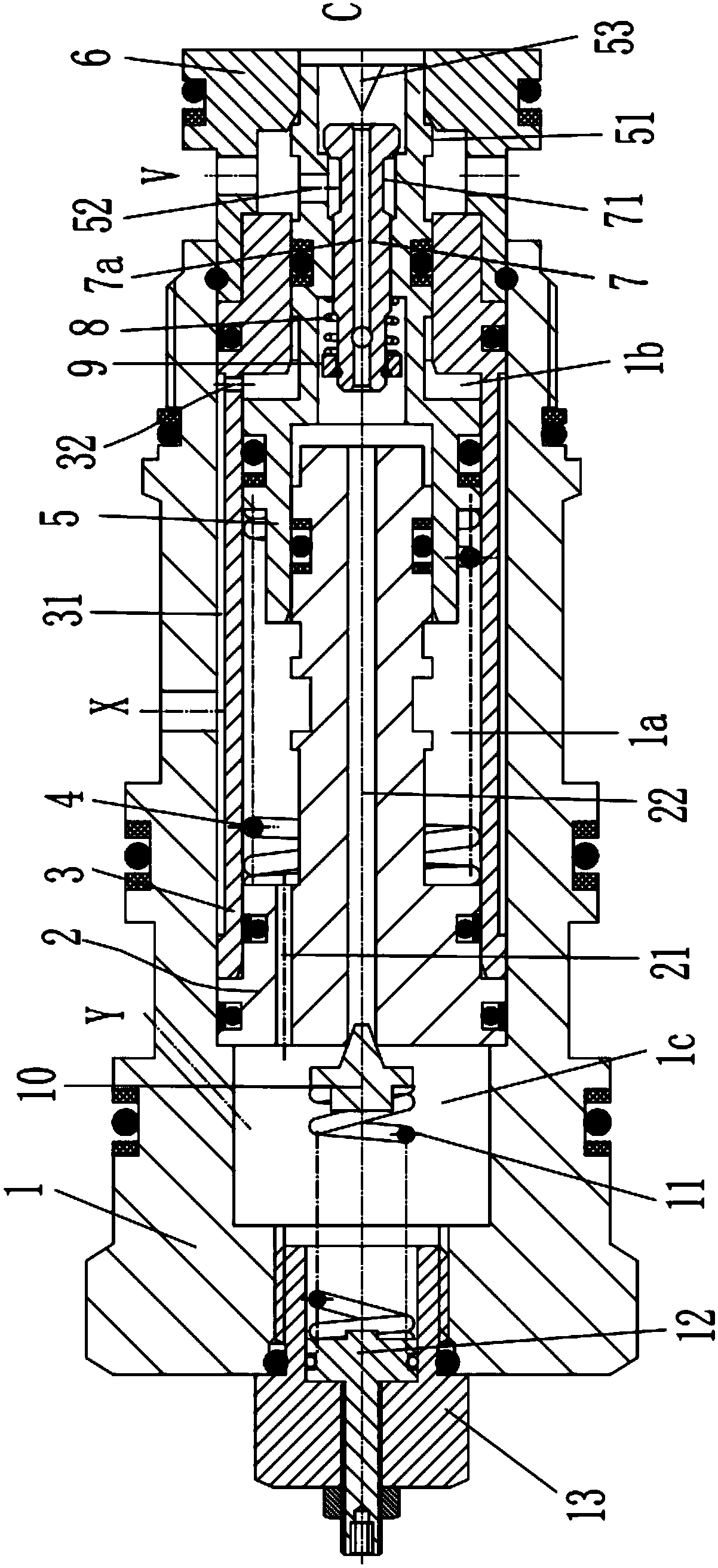
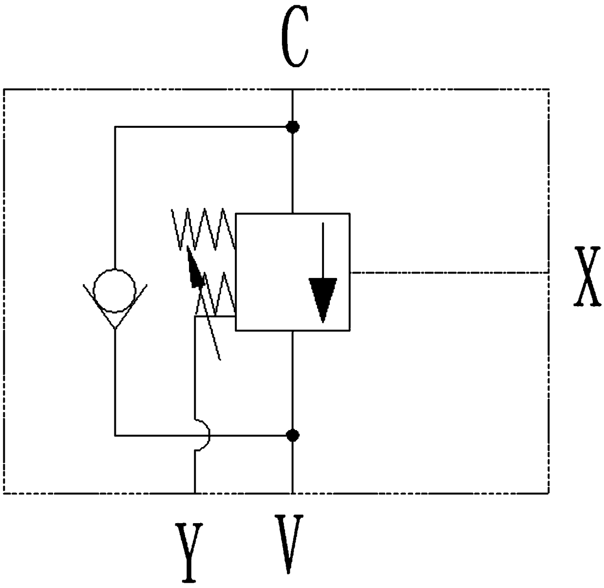
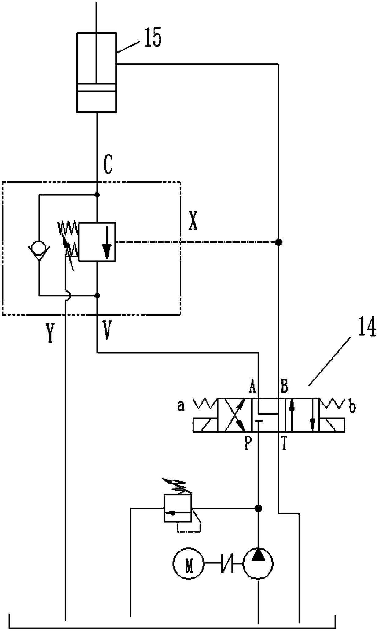
[0028] Such as Figure 1 to Figure 3 As shown, the plug-in balance valve according to the embodiment of the present invention includes: valve seat 6, valve casing 1, valve sleeve 3, balance valve core 5, check valve core 7, stop ring 9, first spring 8, compensation Plunger 2, second spring 4, overflow valve assembly.

[0029] Specifically, the valve seat 6 ...


PUM


Abstract

The invention provides a cartridge balance valve comprising a valve seat, a valve shell, a valve sleeve, a balance valve element, a one-way valve element, a baffle ring, a first spring, a compensatingplunger, a second spring and an overflow valve assembly. According to the cartridge balance valve, machining is easy, the overflowing area has no sudden change, the safety protection function can bequickly achieved, and the service life is long.

Description

technical field [0001] The invention relates to a valve assembly for a hydraulic device, in particular to a plug-in balance valve. Background technique [0002] In modern construction machinery, construction machinery and other mechanical equipment, a large number of lifting hydraulic circuits are used. Among them, the balance valve is the key hydraulic component that controls the work of the hydraulic cylinder in the lifting circuit. The performance of the balance valve directly affects the performance of the main engine. [0003] The existing hydraulic balance valve generally has such a shortcoming: when the load is lowered, due to the characteristics of sudden changes in the flow area of ​​the valve port of the hydraulic balance valve, it will cause low-frequency jitter and impact on the load, resulting in system instability and affecting the overall performance. The safety and reliability of the machine; and during the working process of the oil cylinder, because the bal...

Claims


Application Information

Patent Timeline
IPC IPC(8): F15B13/02
CPCF15B13/023
Inventor 不公告发明人
Owner 佛山信卓派思机械科技有限公司
Why Eureka
Try Eureka