
Low-rate and high-rate concentrating solar cell

A technology of solar cells and high concentration light, applied in the field of energy saving and emission reduction, can solve the problems of high cost, single use method, inconvenient use, etc., and achieve the effect of convenient operation and simple structure

Inactive Publication Date: 2018-11-20
WENLING JIUXIN IOT TECH CO LTD
View PDF0 Cites 0 Cited by
  • Summary
  • Abstract
  • Description
  • Claims
  • Application Information

AI Technical Summary

Problems solved by technology

[0002] With the development of society, electric energy is becoming more and more important, and the demand is also increasing. Especially in summer, power failures or power outages occur from time to time, so emergency power is needed. The cost of existing emergency power devices is relatively high. Moreover, it is inconvenient to use, and the use method is single at the same time. Therefore, it is necessary to design a low-power and high-power concentrating solar cell. This device not only uses concentrating solar power, but also can choose low power or high power concentrating power according to the intensity of the sun. , it can be used for emergency power generation for efficient power generation, and it can also be used for outdoor power supply. At the same time, it can be stored to a certain extent, and it can be protected to a certain extent when it is not in use.

Method used

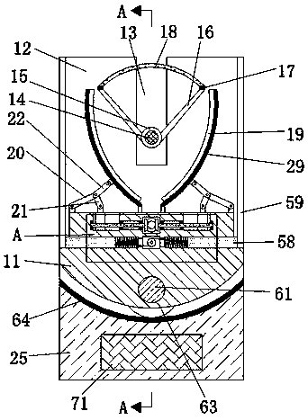
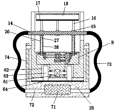

Image

  • Low-rate and high-rate concentrating solar cell
  • Low-rate and high-rate concentrating solar cell
  • Low-rate and high-rate concentrating solar cell

Examples


Embodiment Construction

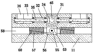
[0015] Such as Figure 1-Figure 4As shown, a low-power and high-power concentrating solar cell of the present invention includes a first device main body 11, a light concentrating device arranged in the first device main body 11, and a transmission device arranged on the lower side of the transmission device , a stretching device arranged on the lower side of the transmission device and an adjustment device arranged under the stretching device, the transmission device includes a first transmission cavity 31 arranged in the first device main body 11, the first The inner walls of the left and right sides of the transmission chamber 31 are symmetrically and connected with a first through hole 32, and the side of the first through hole 32 away from the first transmission chamber 31 is connected with a first slide chamber 33. A first gear 34 is symmetrically arranged in the first transmission chamber 31, and the opposite side of the first gear 34 is fixedly connected to the first t...


PUM


Abstract

The invention discloses a low-rate and high-rate concentrating solar cell. The low-rate and high-rate concentrating solar cell comprises a first device main body, a condensation device, a transmissiondevice, an expansion device and an adjustment device and is characterized in that the condensation device is arranged in the first device main body, the transmission device is arranged at a lower side of the transmission device, the expansion device is arranged at a lower side of the transmission device, the adjustment device is arranged under the expansion device, the transmission device comprises a first transmission cavity, the first transmission cavity is formed in the first device main body, first through holes are symmetrically formed in inner walls of a left side and a right side of the first transmission cavity and communicate with each other, and a first sliding cavity is formed in one side, far away from the first transmission cavity, of each first through hole in a communication way. The device can select low-rate or high-rate concentrating power generation according to solar intensity, high-efficiency power generation can be achieved when the device is used for emergency power generation, and meanwhile, the device also can be used for supplying power in the outside, can be stored to a certain extent and can be protected to a certain extent when not used.

Description

technical field [0001] The invention relates to the technical field of energy saving and emission reduction, in particular to a low-power and high-power concentrated solar cell. Background technique [0002] With the development of society, electric energy is becoming more and more important, and the demand is also increasing. Especially in summer, power failures or power outages occur from time to time, so emergency power is needed. The cost of existing emergency power devices is relatively high. And it is inconvenient to use, and the use method is single at the same time, so it is necessary to design a low-power and high-power concentrating solar cell. This device not only uses concentrating solar power, but also can choose low or high power concentrating power according to the intensity of the sun. , It can generate high-efficiency power generation when used for emergency power generation, and can also be used for outdoor power supply. At the same time, it can be stored t...

Claims


Application Information

Patent Timeline
IPC IPC(8): H02S40/22
CPCH02S40/22Y02E10/52
Inventor 吴娜
Owner WENLING JIUXIN IOT TECH CO LTD
Learn More