Fluid damper device and apparatus with damper

一种流体阻尼、阻尼室的技术,应用在流体阻尼装置及带阻尼的设备领域,能够解决旋转负载大等问题,达到变形的可能性小、抑制阻尼性能的不均、提高尺寸精度的效果

Active Publication Date: 2018-11-23
SANKYO SEIKI MFG CO LTD
View PDF8 Cites 2 Cited by
  • Summary
  • Abstract
  • Description
  • Claims
  • Application Information

AI Technical Summary

Problems solved by technology

Therefore, the rotational load of the rotor is large

Method used


Image

  • Fluid damper device and apparatus with damper
  • Fluid damper device and apparatus with damper
  • Fluid damper device and apparatus with damper

Examples


Embodiment Construction

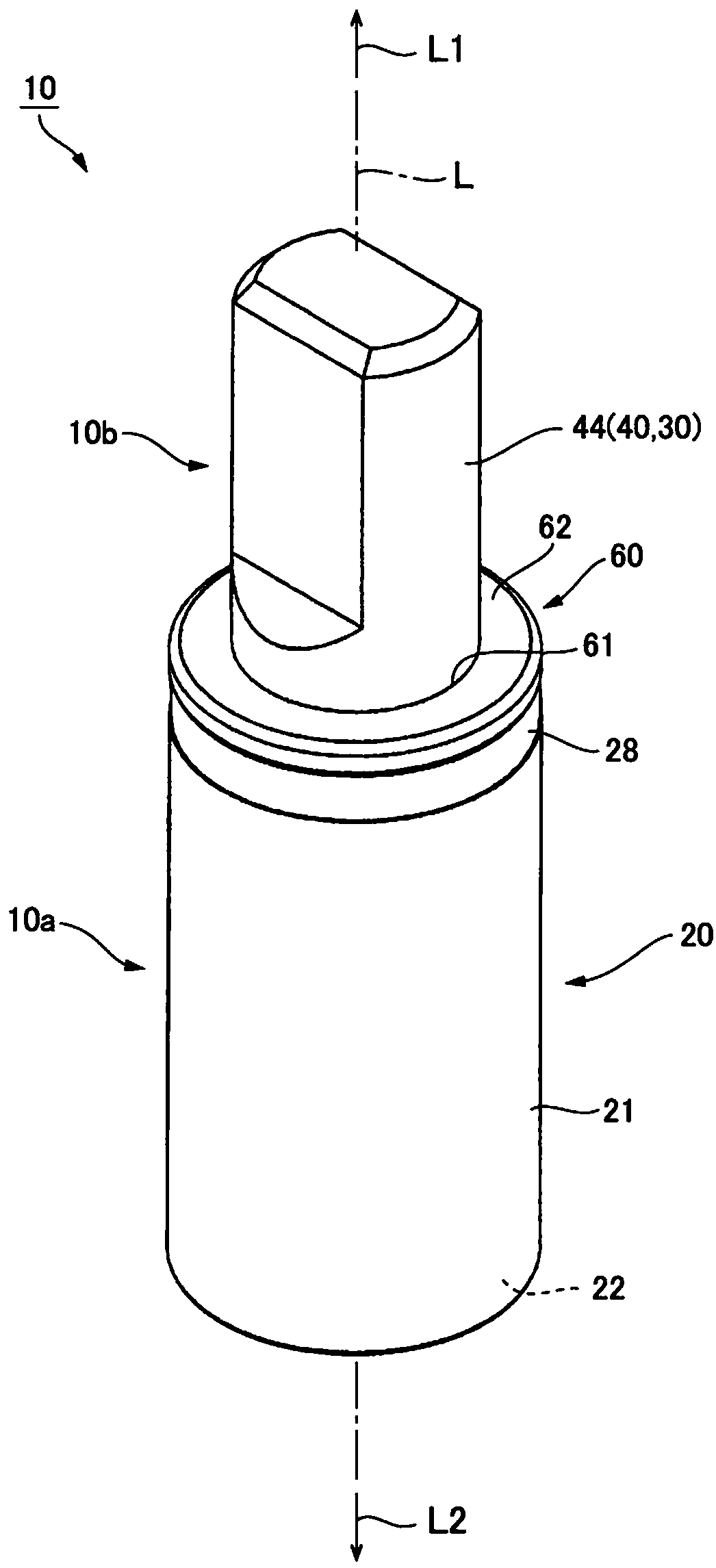
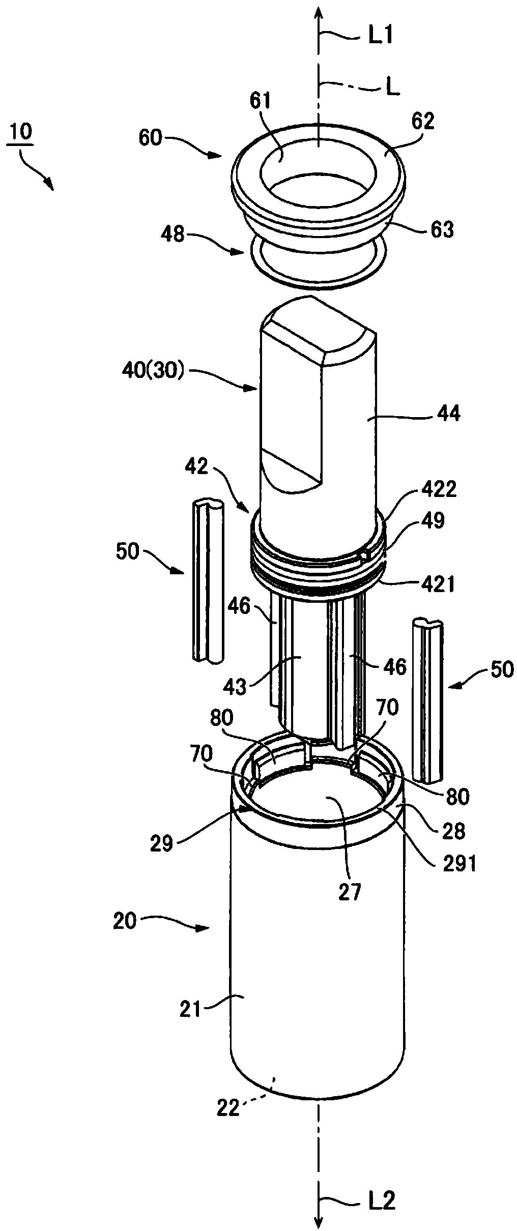
[0115] Hereinafter, modes for implementing the present invention will be described with reference to the drawings. Furthermore, in the following description, the direction in which the rotating shaft 40 of the rotor 30 extends is referred to as the direction of the axis L, and the side where the rotating shaft 40 protrudes from the housing 20 in the direction of the axis L is referred to as one side L1. The side opposite to the side where the rotating shaft 40 protrudes from the casing 20 is described as the other side L2.

[0116] (device with damping)

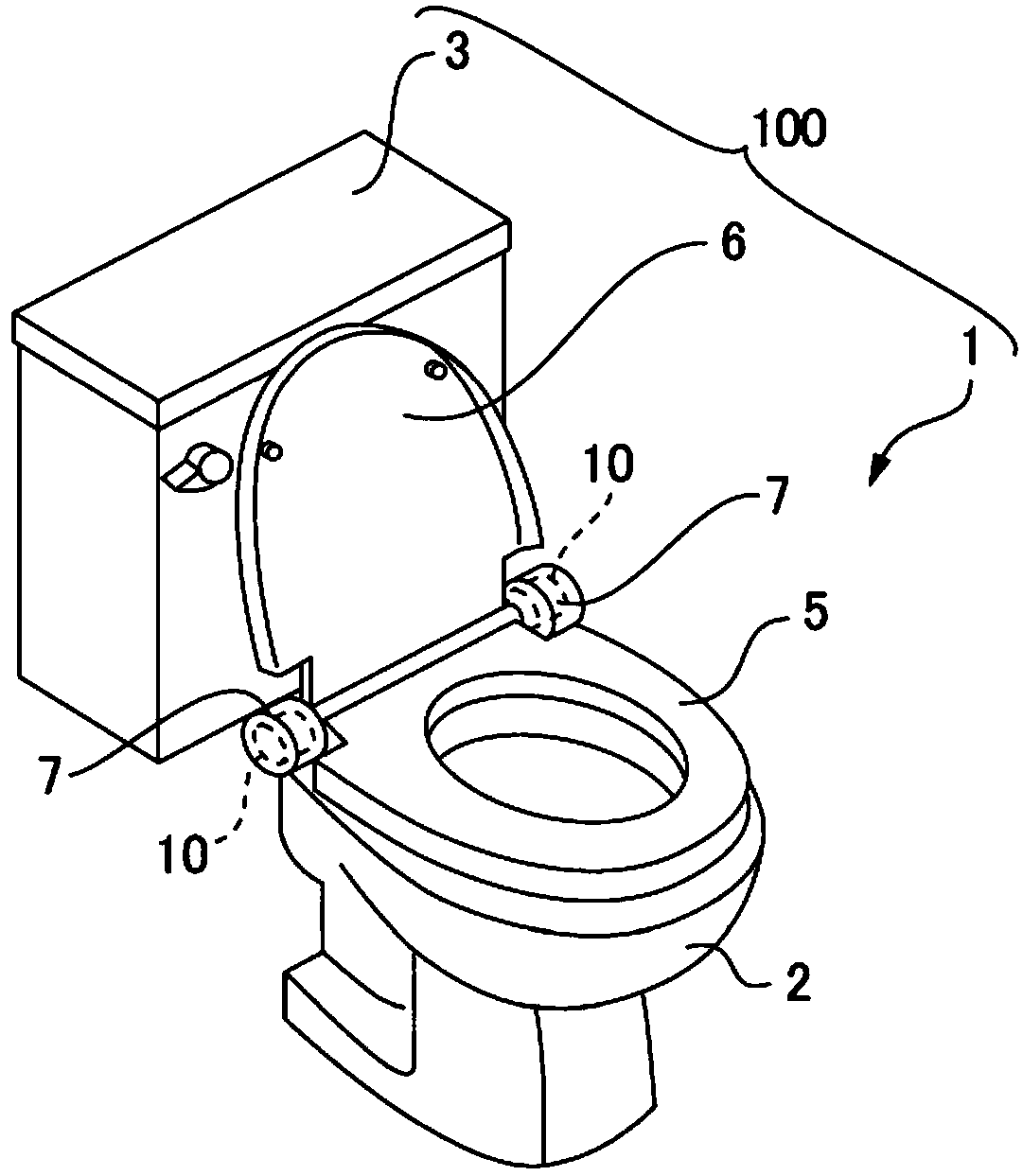
[0117] figure 1It is an explanatory diagram of a western-style toilet unit 100 including a western-style toilet 1 equipped with a fluid damping device 10 to which the present invention is applied. figure 1 The western-style toilet unit 100 shown includes: a western-style toilet 1 (equipment with damping) and a sink 3 . The western-style toilet 1 includes a toilet body 2 (device body), a resin toilet seat 5 (opening and clo...


PUM


Abstract

The invention provides a fluid damper device and apparatus with damper. In the present invention, in the fluid damper device, the lid body is appropriately fixed to the opening of the casing.The fluiddamper device includes a rotor inserted into a case, and a cover fixed to an opening portion of the case. A thin portion is formed at an end portion of the case on one side in an axis direction, anda contact portion which is in contact with a small-diameter portion of the cover in the axis direction is formed at four positions of an inner circumferential surface of the thin portion at equal angular intervals. A partitioning convex portion which partitions a damper chamber in a circumferential direction is formed on an inner circumferential surface of the case, and the contact portions are formed at positions corresponding to the partitioning convex portion in the circumferential direction. A concave portion recessed radially outward is formed at a position different from the contact portion in the circumferential direction, and a welding convex portion is formed in the concave portion.The small-diameter portion is welded to the welding convex portion by ultrasonic welding.

Description

technical field [0001] The invention relates to a fluid damping device and damping equipment in which fluid is filled between a housing and a rotor. Background technique [0002] Patent Document 1 discloses a fluid damper device in which a fluid such as oil is filled between a bottomed cylindrical case and a rotor. In the fluid damping device of Patent Document 1, one end in the axial direction of the rotor (rotation shaft) is arranged inside the housing, a damping chamber is formed between the rotating shaft and the inner peripheral surface of the housing, and a valve body is arranged in the damping chamber. The valve body is arranged on the side of the rotating shaft. When the rotor rotates in the first direction, the radial front end of the valve body contacts the inner peripheral surface of the housing. Therefore, the rotational load of the rotor is large. On the other hand, when the rotor rotates in the direction opposite to the first direction, there will be a gap b...

Claims


Application Information

Patent Timeline
Patent Type & Authority Applications(China)
IPC IPC(8): A47K13/10A47K13/24
CPCA47K13/10A47K13/24E05F5/00E05D3/02A47K13/12E05Y2900/614E05Y2201/266E05D11/06E05Y2201/224F16F9/145F16F9/48E05D11/00F16F9/369F16F2232/02E05Y2201/212F16F9/34F16F2222/12
Inventor 三原直哉
Owner SANKYO SEIKI MFG CO LTD
Why Eureka
Try Eureka