
A particle bed support grid and radial flow reactor

A technology for supporting grids and particles, applied in the separation of dispersed particles, chemical instruments and methods, chemical/physical processes, etc., can solve the problems of inner cylinder instability, wire mesh erosion and corrosion, and low opening ratio of distribution plates

Active Publication Date: 2021-05-18
SINOPEC ENG +1
View PDF8 Cites 0 Cited by
  • Summary
  • Abstract
  • Description
  • Claims
  • Application Information

AI Technical Summary

Problems solved by technology

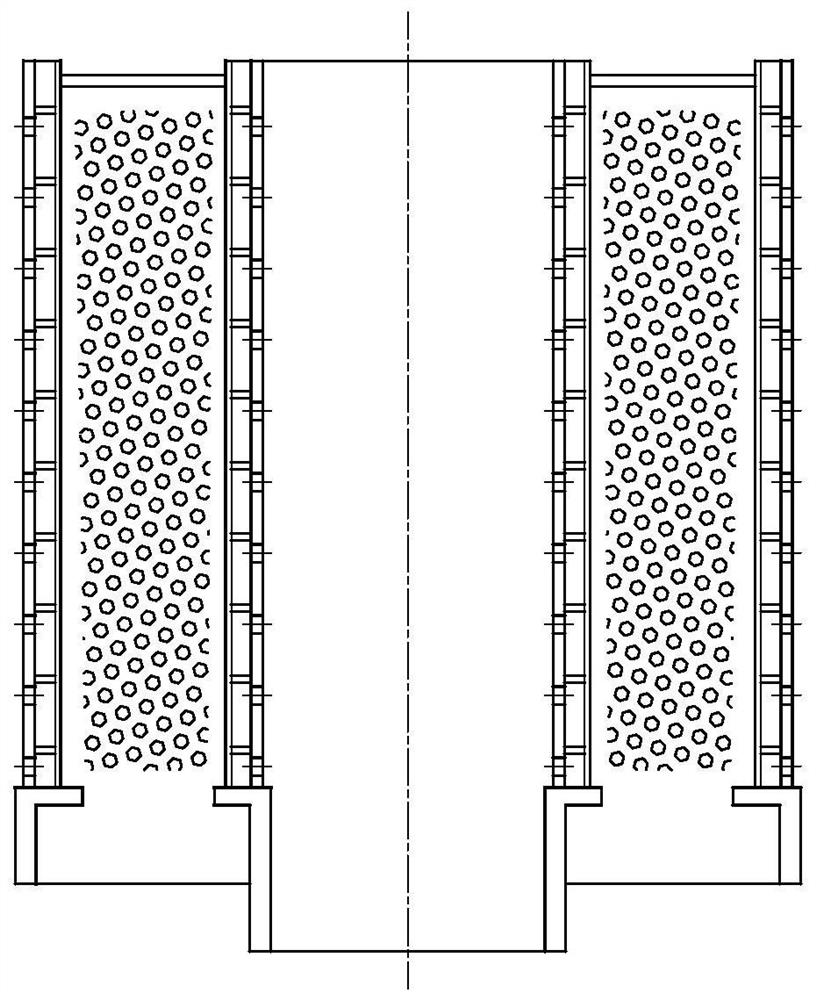
[0004] However, there are three outstanding problems in the inner cylinder grid in the prior art. 1) Due to the limitation of the minimum opening distance, the opening ratio (the ratio of the opening flow area to the total cross-sectional area) on the distribution plate is low, and the medium flow rate is relatively low. Larger pressure drop across distribution plate
2) The flow velocity at the outlet of the opening of the distribution plate is fast, and the scouring effect on the V-shaped screen is obvious, resulting in erosion and corrosion of the screen, which is easy to break after long-term use
3) During the operation of the reactor, the convex surface of the grid of the inner cylinder will bear the pressure from the catalyst, that is, the external pressure. Under the action of the external pressure, the stability and rigidity of the inner cylinder are required to be high, which may easily cause the inner cylinder to become unstable.

Method used


Image

  • A particle bed support grid and radial flow reactor
  • A particle bed support grid and radial flow reactor
  • A particle bed support grid and radial flow reactor

Examples


Embodiment 1

[0050] This example is used to illustrate the particulate matter bed support grid of the present invention.

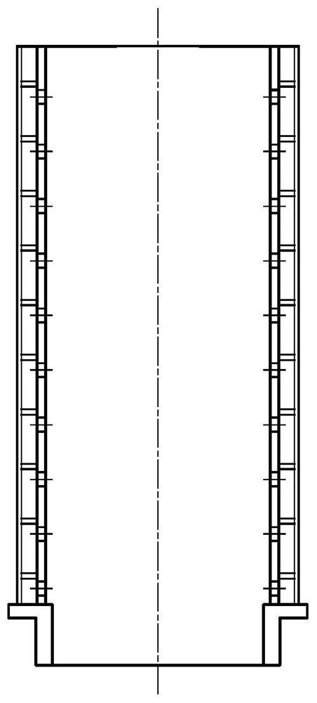
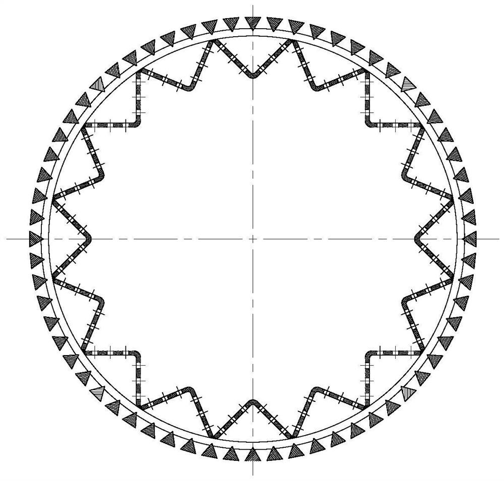
[0051] Such as Figure 3-5 As shown, the granular bed support grid is a double-layer cylindrical structure, which includes a grid tube 1-1 arranged radially, a support rod 1-2, a distribution tube 1-3, and connections at the ends Plate 1-4, the support rod 1-2 is located between the grid cylinder 1-1 and the distribution cylinder 1-3, and the distribution cylinder 1-3 and the grid cylinder 1-1 are welded on the support rod.

[0052] The grid cylinder 1-1 is a circular cylinder composed of a V-shaped wire mesh, the sharp corner of the V-shaped wire mesh faces the distribution cylinder 1-3, and is embedded in the support rod 1-2, and is connected with the support rod 1-2 weld with the flat side facing the particulate bed.

[0053] The distribution cylinder 1-3 is cylindrical as a whole, and the cylinder surface has a wave-shaped structure and is provided with uniformly...

Embodiment 2

[0058] This example is used to illustrate the particulate matter bed support grid of the present invention.

[0059] Such as Figure 6-8 As shown, the granular bed support grid is a double-layer cylindrical structure, which includes a grid tube 1-1 arranged radially, a support rod 1-2, a distribution tube 1-3, and connections at the ends Plate 1-4, the support rod 1-2 is located between the grid cylinder 1-1 and the distribution cylinder 1-3, and the distribution cylinder 1-3 and the grid cylinder 1-1 are welded on the support rod.

[0060] The grid cylinder 1-1 is a circular cylinder composed of a V-shaped wire mesh, the sharp corner of the V-shaped wire mesh faces the distribution cylinder 1-3, and is embedded in the support rod 1-2, and is connected with the support rod 1-2 weld with the flat side facing the particulate bed.

[0061] The distribution cylinder 1-3 is cylindrical as a whole, and the cylinder surface has a wave-shaped structure and is provided with uniformly...

Embodiment 3

[0066] This example is used to illustrate the radial flow reactor of the present invention.

[0067] Such as Figure 11 As shown, the radial flow reactor of the present invention includes an inner cylinder grid 1, an outer cylinder grid 2, a housing 4, an inlet pipe 6, a gas distributor 7, an outlet pipe 5 and a support 8, and is arranged on the The catalyst bed 3 between the inner cylinder grid 1 and the outer cylinder grid 2 .

[0068] The casing 4, the outer cylinder grille 2 and the inner cylinder grille 1 are nested sequentially in the radial direction, the inlet pipe 6 is arranged at the bottom of the casing 4, and the gas distributor 7 is located at the inlet Above the pipe 6, its axis coincides with the axes of the inner cylinder grid 1, the outer cylinder grid 2 and the casing 4, the outlet pipe 5 is arranged on the top of the casing 4, and the support 8 is arranged The inner wall and the bottom of the housing 4 are supported under the inner cylinder grid 1 and the ...


PUM


Abstract

The invention relates to the field of petrochemical equipment, and specifically provides a particle bed support grid and a radial flow reactor. The granular matter bed support grid of the present invention is a double-layer cylindrical structure, which includes a grid cylinder arranged radially, a support rod, a distribution cylinder, and a connecting plate at the end, and the support rod is located between the grid cylinder and the grid cylinder. Between the distribution cylinders, the grid cylinder is a circular cylinder made of V-shaped wire mesh. The distribution cylinder is in the shape of a cylinder as a whole, and the surface of the cylinder has a wave-shaped structure and is provided with through holes. The particle bed support grid can make the flow velocity distribution of the inlet fluid more uniform; it can reduce the impact of the fluid on the V-shaped screen and prolong the service life of the V-shaped screen; it also has a high bearing capacity and resistance to external pressure instability. It is suitable for reaction, adsorption, drying or purification equipment that requires high fluid distribution uniformity, large processing capacity, large bed filling capacity, and strict bed pressure drop.

Description

technical field [0001] The invention relates to the field of petrochemical equipment, in particular to a particle bed support grid and a radial flow reactor using the particle bed support grid. Background technique [0002] The catalyst bed support structure of the reactor is generally divided into two types, namely, a planar support grid and a cylindrical support grid. These two support structures correspond to axial flow reactors and radial flow reactors, respectively. [0003] Cylindrical grid support structures such as figure 1 As shown, it is generally used in radial flow reactors with fluidized bed or fixed bed. The gas flow direction of this type of reactor is perpendicular to the axial direction of the equipment, and the cylindrical grid is arranged vertically, including the inner cylinder grid and the outer cylinder grid (or fan-shaped cylinder), and the catalyst bed is located between the inner cylinder and the outer cylinder. The vertical annular space is mostl...

Claims


Application Information

Patent Timeline
Patent Type & Authority Patents(China)
IPC IPC(8): B01J8/02B01D53/04B01D53/26
CPCB01D53/0431B01D53/26B01J8/008B01J8/0214B01J2208/00884
Inventor 郭雪华高晖冯清晓张铁钢元少昀闫晶怡利梅
Owner SINOPEC ENG
Learn More