Production technology of engine bearing bush

A production process and engine technology, applied in the direction of bearing components, shafts and bearings, mechanical equipment, etc., can solve the uneven coating on the surface of the workpiece to be plated, the inability to complete the clamping of different types of parts, and affect the sputtering quality of the workpiece to be plated, etc. problems, to achieve the effect of ensuring reliability, simple clamping process and high efficiency

Active Publication Date: 2018-11-23
日照菁英传媒科技有限公司
View PDF6 Cites 4 Cited by
  • Summary
  • Abstract
  • Description
  • Claims
  • Application Information

AI Technical Summary

Problems solved by technology

[0004] The sputtering device in this technical solution can place more workpieces to be plated and improve the coating efficiency, but the material rod in the device can only be rotated around the central axis, resulting in that one side of the workpiece to be plated cannot accept the attachment of ions , which in turn leads to uneven coating on the surface of the workpiece to be plated, which ultimately affects the sputtering quality of the workpiece to be plated; this device cannot complete the clamping of different types of parts

Method used


Image

  • Production technology of engine bearing bush
  • Production technology of engine bearing bush
  • Production technology of engine bearing bush

Examples


Embodiment Construction

[0032] In order to make the technical means, creative features, goals and effects achieved by the present invention easy to understand, the present invention will be further described below in conjunction with specific embodiments.

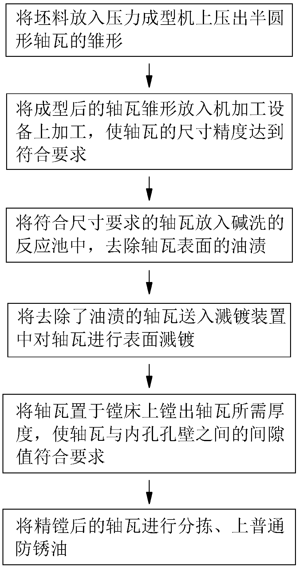
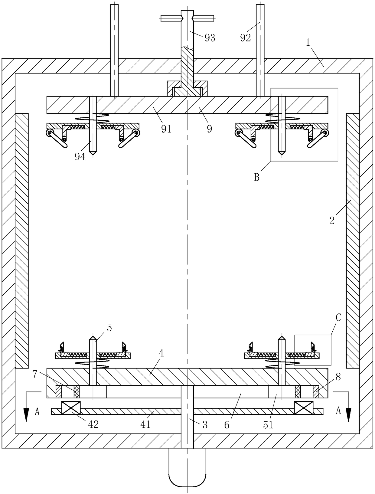
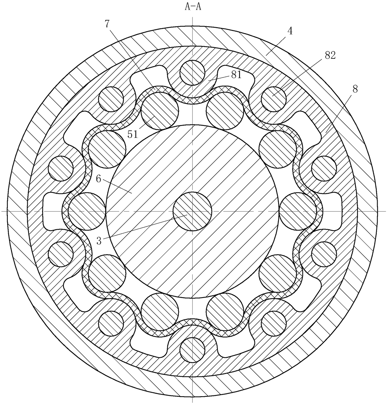
[0033] Such as Figure 1 to Figure 5 Shown, the production technology of a kind of engine bearing bush of the present invention, this method comprises the steps:

[0034] Step 1: Put the blank into the pressure forming machine and press out the prototype of the semicircular bearing bush;

[0035] Step 2: Put the prototype of the bearing pad formed in step 1 into the machining equipment for processing, so that the dimensional accuracy of the bearing pad meets the requirements;

[0036] Step 3: Put the bearing bush that meets the size requirements in step 2 into the reaction pool for alkali cleaning to remove the oil stain on the surface of the bearing bush;

[0037] Step 4: Send the bearing bush from which oil stains have been removed in step 3 t...


PUM


Abstract

The invention belongs to the technical field of bearing bushes, and particularly relates to a production technology of an engine bearing bush. A sputtering coating device used in the technology comprises a shell, a target material, a motor, a connection shaft, a lower supporting disc, a thimble, a friction wheel, a friction belt, an extrusion ring and a driven supporting module, wherein the friction wheel is fixedly connected with the upper end of the connection shaft; the lower supporting disc is arranged above the friction wheel; and the outer side surface of the extrusion ring is fixedly connected to the interior of a cylindrical groove in the lower supporting disc. The surface of a round disc at the lower end of the thimble is arranged to be in contact with the cylindrical surface of the friction wheel, a semispherical bulge on the extrusion ring and the round disc at the lower end of the thimble are alternately arranged, the friction belt is arranged between the extrusion ring andthe round disc at the lower end of the thimble, the driven supporting module is arranged at the upper end of the shell, the purpose that a to-be-plated workpiece above the lower supporting disc rotates around the connection shaft and self-rotates around the thimble is achieved, so that the surface of the to-be-plated workpiece can uniformly receive the ions impacted to the target material, and accordingly uniform sputtering and coating of the surface of a shaft part is achieved.

Description

technical field [0001] The invention belongs to the technical field of bearing bush production, in particular to a production process of a bearing bush for an engine. Background technique [0002] The bearing bush is a component used to protect the shaft. Sliding bearings for internal combustion engines mainly include bearing bushes, bushings, flanged bushes and thrust plates. For high-speed, heavy-duty, high-precision, and structurally divided occasions, sliding bearings are required, such as steam turbines, centrifugal compressors, internal combustion engines, and large motors. The part that supports the journal in the bearing is the bearing bush, so the bearing bush is an important part in the sliding bearing. The bearing pad is one of the most critical parts of the engine, and the performance of the bearing pad directly affects the performance of the engine. With the development of internal combustion engines in the direction of high speed, high load, and environmenta...

Claims


Application Information

Patent Timeline
Patent Type & Authority Applications(China)
IPC IPC(8): B23P15/00F16C33/02
CPCB23P15/00F16C33/02
Inventor 王志伟
Owner 日照菁英传媒科技有限公司
Why Eureka
Try Eureka