
Multi-angle internal corner deformed abrasive paper frame and using method thereof
A multi-angle, sandpaper technology, applied in the direction of grinding racks, machine tools suitable for grinding workpiece planes, grinding machines, etc., can solve the problems of increasing the complexity of operations, not grinding sharp corners in place, and grinding corners not straight, etc., to achieve Solve grinding difficulties, simplify the steps of grinding, and use simple effects
- Summary
- Abstract
- Description
- Claims
- Application Information
AI Technical Summary
Problems solved by technology
Method used
Image

Examples
Embodiment Construction
[0030] The present invention will be further described below in conjunction with the accompanying drawings.
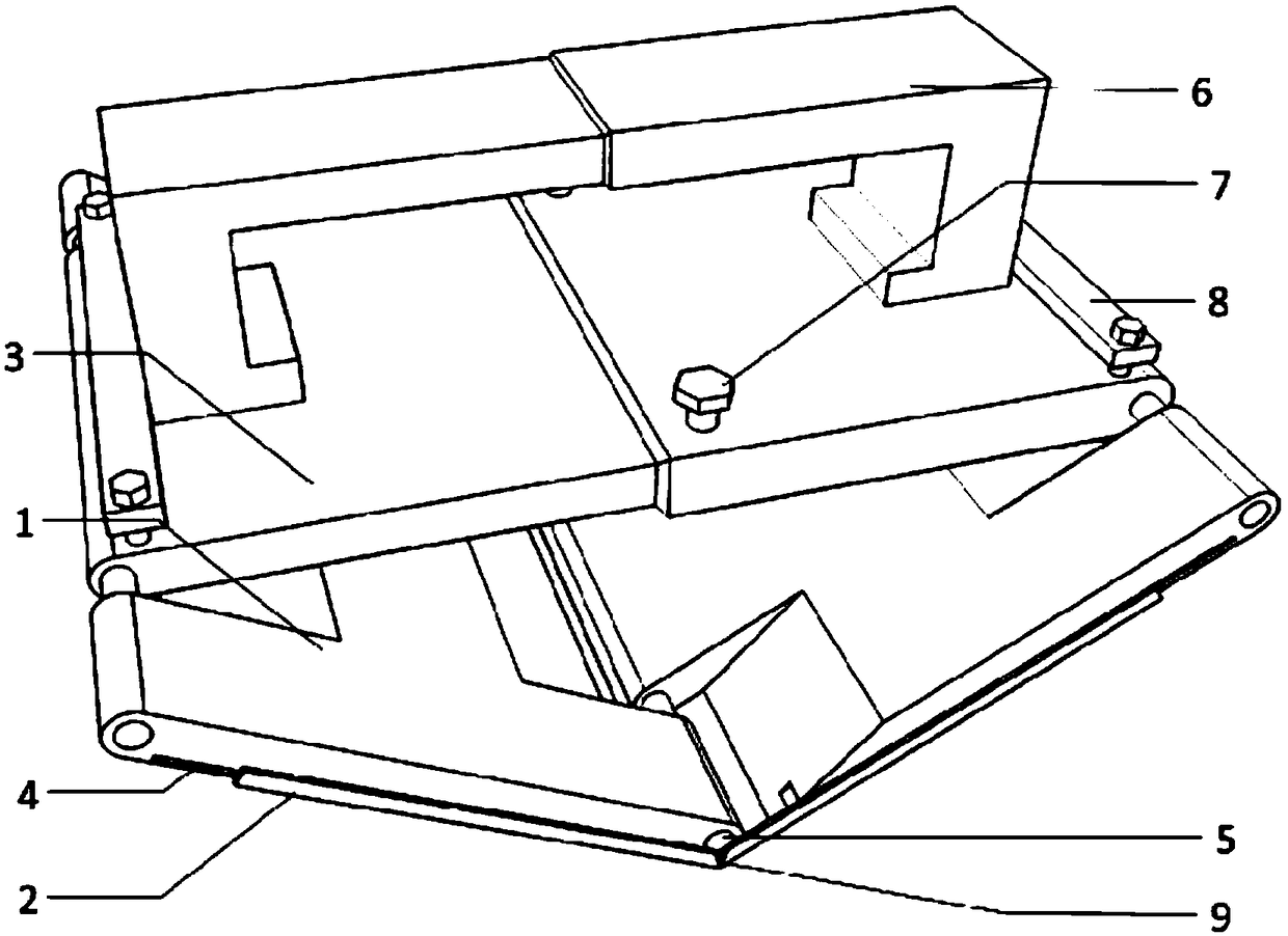
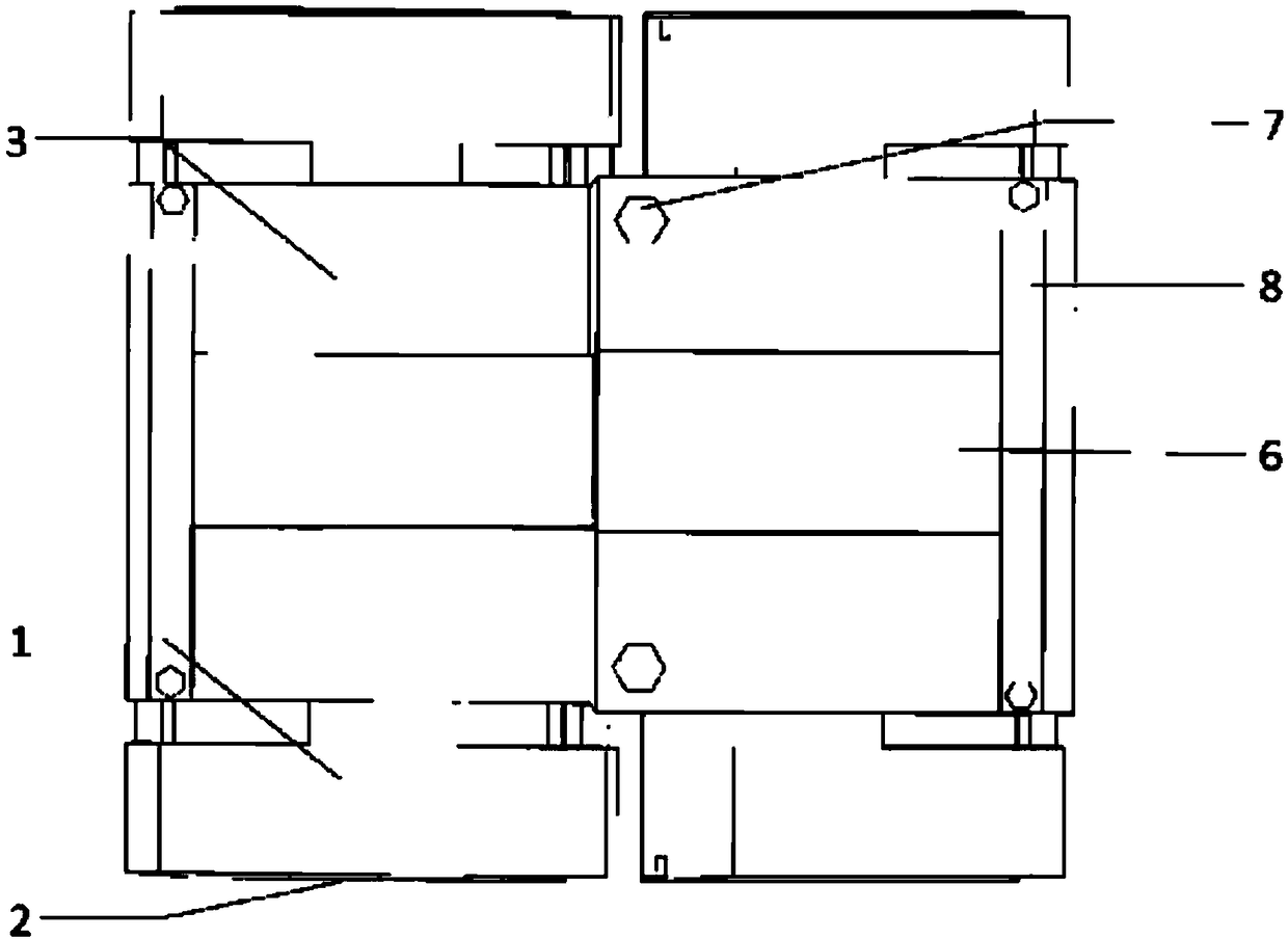
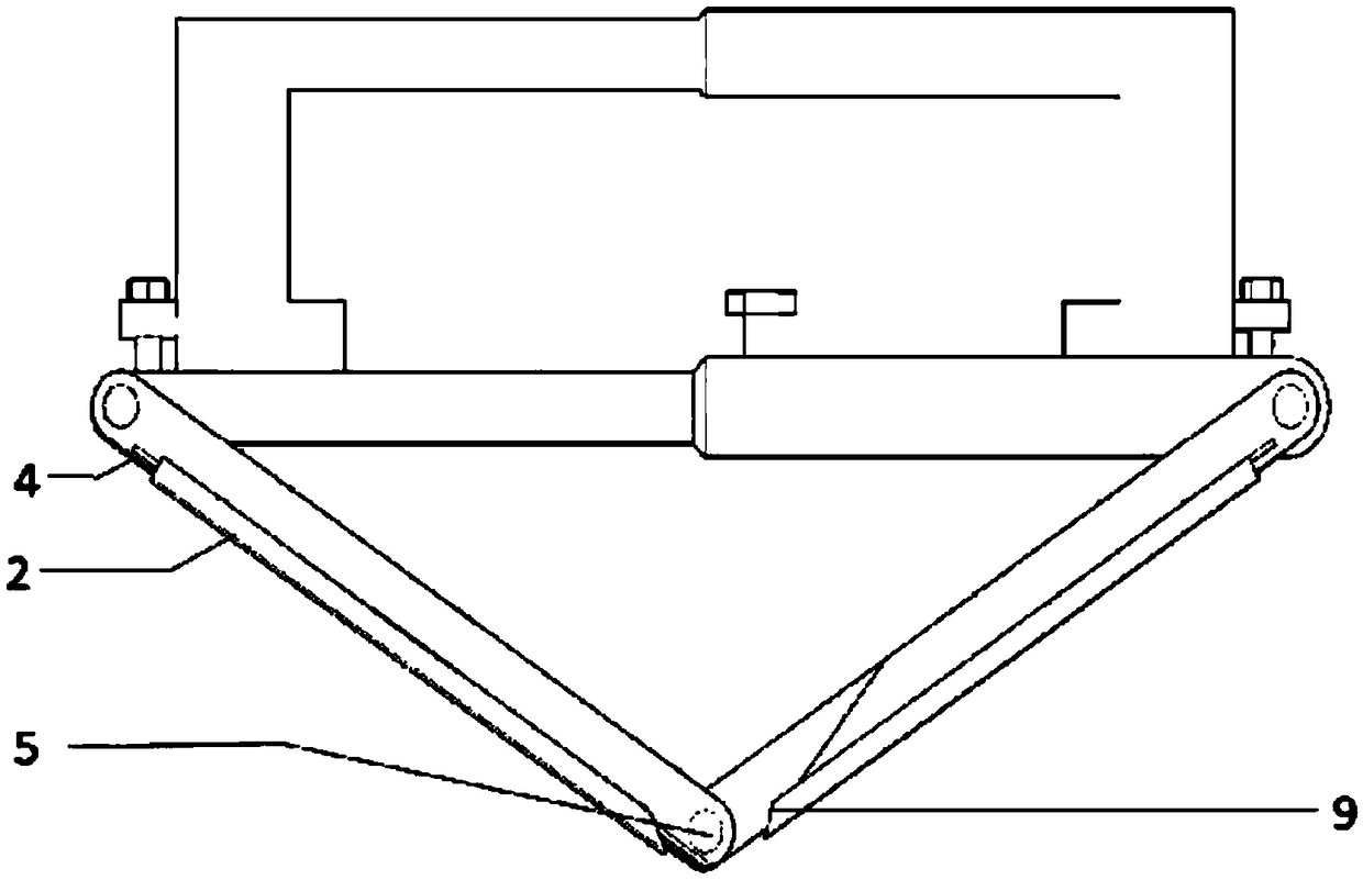
[0031] Such as Figure 1 to Figure 6 As shown, a kind of multi-angle internal angle deformed sandpaper frame of the present invention comprises the first base plate 1 and the second base plate of hinged connection, the first base plate 1 and the second base plate are the rectangular plate of 13cm*20cm, between two base plates Punch holes on both sides, one removes 14cm in the middle of both sides, removes 14cm in the middle of the other side, removes 40cm at both ends of the other side, and perforates with pin 5 in between. When the first bottom plate 1 and the second bottom plate are rotating There will be no interference. The movable end of the first bottom plate 1 and the second bottom plate is hingedly connected with a telescopic plate 3, and the telescopic plate 3 and the two bottom plates are hinged through the holes of the pin 5, and the part of the hinged part...
PUM
 Abstract
Description
Claims
Application Information