A two-body balance valve with a valve body and a valve seat

A technology for balancing valves and valve bodies, which is applied in the field of balancing valves, and can solve problems such as poor preheating before welding and heat treatment after welding, cracks on the sealing surface of hard alloy surfacing welding, complex mechanical processing procedures of valve bodies, etc., and shorten maintenance Time, reliable performance, and the effect of improving labor productivity

Inactive Publication Date: 2016-08-24
CHENGDE HIGH & MIDDLE PRESSURE VALVE PIPE FITTING
View PDF4 Cites 0 Cited by
  • Summary
  • Abstract
  • Description
  • Claims
  • Application Information

AI Technical Summary

Problems solved by technology

[0003] The valve body and the valve seat used in the prior art balance valve have an integral structure, the effect of pre-weld preheating and post-weld heat treatment is poor when the sealing surface of the valve seat is overlay welded with this structure, and the valve body has more sequences in the process of overlay welding and heat treatment , the machining process of the valve body is complicated, and cracks may appear on the hard alloy surfacing sealing surface
The integrated structure of the valve body and valve seat is troublesome to maintain. The entire valve needs to be removed from the pipeline during maintenance. The maintenance operation is complicated, the maintenance time is long, and the cost is high, which makes the operating cost of the balance valve high.
Another disadvantage of the integral structure of the valve body and valve seat is that it is difficult to grind the sealing surface of the valve body, and the grinding quality and efficiency of the valve are low.

Method used


Image

  • A two-body balance valve with a valve body and a valve seat
  • A two-body balance valve with a valve body and a valve seat
  • A two-body balance valve with a valve body and a valve seat

Examples


Embodiment Construction

[0027] The principles and features of the present invention are described below in conjunction with the accompanying drawings, and the examples given are only used to explain the present invention, and are not intended to limit the scope of the present invention.

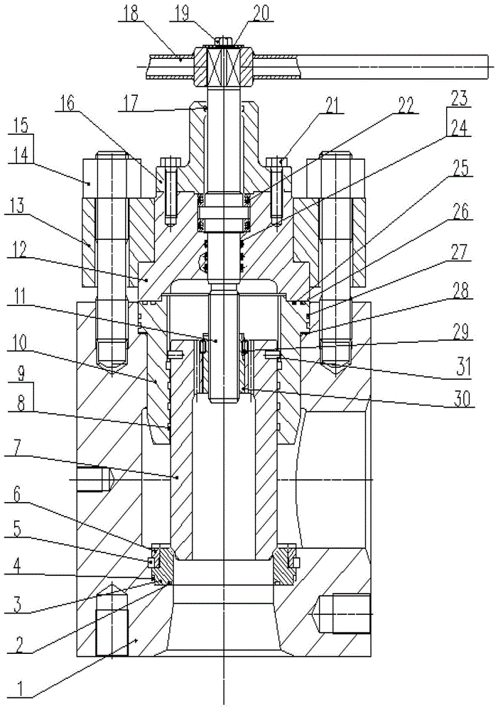
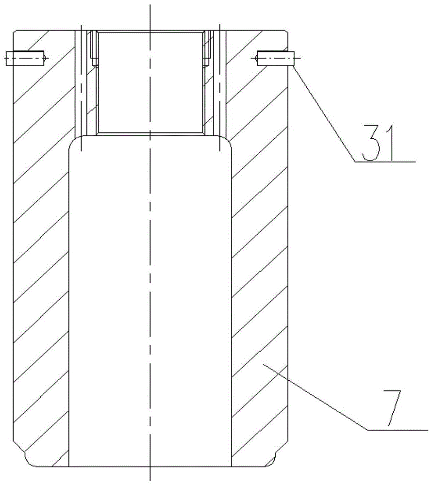
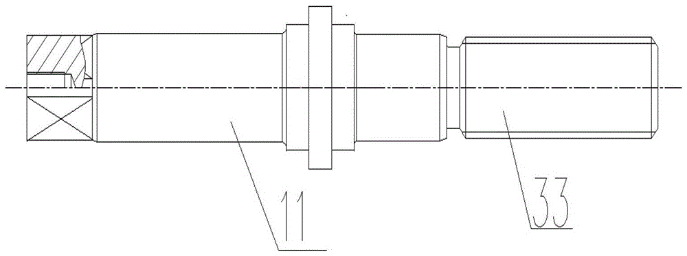
[0028] Such as figure 1 , figure 2 , image 3 , Figure 4 As shown, the valve body 1 is located at the lowermost end of the entire balance valve. A detachable valve seat 3 is installed at the lower end of the inner cavity of the valve body 1. A bushing 6 is installed on the upper end of the outer surface of the valve seat 3. The outer surface of the bushing 6 The lower end of the Liuhe ring 5 is installed, one end of the Liuhe ring 5 is built in the valve body 1, the other end is in the bushing 6, the outer surface of the valve seat 3 is equipped with an O-ring 4, and the bottom surface of the valve seat 3 is installed with an O-ring. type sealing ring 2. The upper end of the inner cavity of the valve body 1 is...


PUM


Abstract

The invention relates to the technical field of hydraulic control, in particular to a balance valve with separated valve body and valve seat. The technical scheme is as follows: the balance valve with the valve body and the valve seat separated comprises the valve body, the valve seat, an upper gland box, a lower gland box, a valve rod and a valve clack, wherein the lower gland box is arranged in the valve body, the upper gland box is arranged on the lower gland box, the valve cover is fixed on the upper gland box, the valve rod extends into a valve body cavity through the valve cover, the valve clack is arranged at the lower part of the valve rod, the lower end of the valve body cavity is provided with the detachable valve seat, the outer side surface of the valve seat is provided with a liner, a six-element rig is arranged at the lower end of the outer side surface of the liner, one end of the six-element ring is in the valve body, the other end of the six-element ring is in the liner, and both the outer side surface and the bottom surface of the valve seat are provided with seal rings. The balance valve with separated valve body and valve seat is convenient to operate and simple to process, is high in maintenance speed and good in valve sealing effect, and can be used in the mechanical grinding of a seal surface of the valve body.

Description

technical field [0001] The invention relates to the technical field of hydraulic control, in particular to a two-piece valve body and valve seat (that is, the valve body and the valve seat can be separated into two parts structurally) balance valve. Background technique [0002] In some industries, due to the large pressure difference or flow difference of the medium (various flowable substances) in various parts of the pipeline or container, in order to reduce or balance the difference, install between the corresponding pipelines or containers A valve is provided to adjust the relative balance of the pressure on both sides, or to achieve flow balance through the method of diversion. The valve is called a balance valve. Due to the opening of the valve clack, the high-pressure medium can enter the balance chamber formed by the lower stuffing box and the valve clack through the small hole of the valve clack, and balance the force of the medium acting on the sealing surface of ...

Claims


Application Information

Patent Timeline
Patent Type & Authority Patents(China)
IPC IPC(8): F16K1/42
Inventor 玉金贵站永富翁兆德顾春辉
Owner CHENGDE HIGH & MIDDLE PRESSURE VALVE PIPE FITTING
Why Eureka
Try Eureka