Cylinder head clamping device

A technology of cylinder head and clamping block, which is applied in the direction of grinding/polishing safety devices, chucks, metal processing equipment, etc., which can solve the damage of the inner wall of the cylinder head, the large force on the cylinder head, and the small contact area between the cylinder head and the inserting arm and other problems, to achieve the effect of reducing processing steps, solving grinding difficulties, and improving work efficiency

Active Publication Date: 2019-04-19
山东宇生文化股份有限公司
View PDF1 Cites 0 Cited by
  • Summary
  • Abstract
  • Description
  • Claims
  • Application Information

AI Technical Summary

Problems solved by technology

However, there are still defects in this invention: to carry the cylinder head, the insertion arm is inserted into the hole by adjusting the insertion arm, and then the two insertion arms are opened for transportation. The contact area between the cylinder head and the insertion arm is small, and the force on both sides of the cylinder head is too large. It is easy to damage the inner wall of the cylinder head

Method used


Image

  • Cylinder head clamping device

Examples


Embodiment Construction

[0017] The present invention will be further described in detail below through specific implementations:

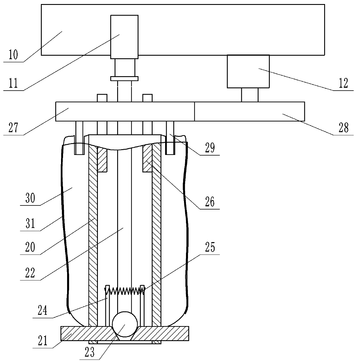
[0018] The reference signs in the drawings of the specification include: frame 10, cylinder 11, motor 12, clamping rod 20, telescopic clamping block 21, push rod 22, push ball 23, gear rod 24, ring spring 25, fixed shaft 26, The first gear 27, the second gear 28, the rotating rod 29, the air bag 30, and the sanding belt 31.

[0019] Such as figure 1 As shown, the cylinder head clamping device includes a frame 10, a clamping rod 20 and an airbag 30. The clamping rod 20 is fixed on the frame 10, the surface of the clamping rod 20 is provided with an annular groove, and the airbag 30 is sleeved in The annular groove can rotate along the annular groove. The upper surface of the airbag 30 is provided with grooves. The outer wall of the airbag 30 is provided with sand belts 31 at intervals. The outer wall of the airbag 30 is also connected with a truncated cone-shaped plug. The sm...


PUM


Abstract

The invention belongs to the technical field of chucks with gripper components, and in particular, discloses a cylinder cover clamping device. The cylinder cover clamping device comprises a frame, a clamping rod fixed on the frame, and an airbag rotationally connected with the clamping rod; a groove is formed in the upper surface of the airbag; the outer wall of the airbag is connected with a plug automatically opened when the pressure exceeds a certain value; a rough layer is arranged on the outer wall of the airbag; a through hole is axially formed in the clamping rod; the clamping rod is radially provided with multiple extension clamping blocks capable of sliding; the inner wall of the through hole is fixedly connected with a fixed shaft; the upper part of the fixed shaft is fixed on the frame; the fixed shaft is rotationally connected with a first gear; a rotating rod for extending into the groove is arranged on the lower surface of the first gear; a motor is fixed on the frame; and an output shaft of the motor is connected with a second gear engaged with the first gear. The cylinder cover clamping device can effectively clamp a cylinder cover, and cannot damage the inner wall of the cylinder cover in the cylinder cover carrying process.

Description

Technical field [0001] The invention belongs to the technical field of chucks with gripping members, and particularly relates to a cylinder head clamping device. Background technique [0002] The cylinder head is installed on the cylinder block to seal the cylinder from above and form the combustion chamber. The cylinder head is also equipped with intake and exhaust valve seats, valve guide holes for installing intake and exhaust valves, as well as intake and exhaust passages. [0003] The cylinder head is usually made of aluminum alloy with light weight and good mechanical properties. However, the volume of the cylinder head is relatively large, and the total weight is still heavier. In the process of processing the cylinder head, the handling of the cylinder head is usually carried out by a mechanical arm. The arm often scratches or damages the cylinder head during operation, causing the cylinder head to be scrapped, causing great economic losses and waste of resources. [0004] ...

Claims


Application Information

Patent Timeline
Patent Type & Authority Patents(China)
IPC IPC(8): B25J15/00B25J15/02B24B5/08B24B55/06
CPCB24B5/08B24B55/06B25J15/0095B25J15/0213
Inventor 荣贵学
Owner 山东宇生文化股份有限公司
Why Eureka
Try Eureka