Automatic uniform discharging control method and device

A control method and uniform technology, applied in the direction of transportation and packaging, loading/unloading, conveyors, etc., can solve the problems of unbalanced material level and the inability to automatically realize uniform discharge of buffer bins, etc.

Active Publication Date: 2018-11-23
ZHONGYE-CHANGTIAN INT ENG CO LTD +1
View PDF5 Cites 9 Cited by
  • Summary
  • Abstract
  • Description
  • Claims
  • Application Information

AI Technical Summary

Problems solved by technology

In the existing unloading plate drive, the time control method is generally adopted. According to a certain unloading sequence, the unloading of the conveyor is controlled based on the set unloading time. The longer the unloading time of the unloading plate, the greater the amount of unloading. Many,

Method used


Image

  • Automatic uniform discharging control method and device
  • Automatic uniform discharging control method and device
  • Automatic uniform discharging control method and device

Examples


Embodiment Construction

[0064] The following will clearly and completely describe the technical solutions in the embodiments of the present invention with reference to the accompanying drawings in the embodiments of the present invention. Obviously, the described embodiments are only some, not all, embodiments of the present invention. Based on the embodiments of the present invention, all other embodiments obtained by persons of ordinary skill in the art without making creative efforts belong to the protection scope of the present invention.

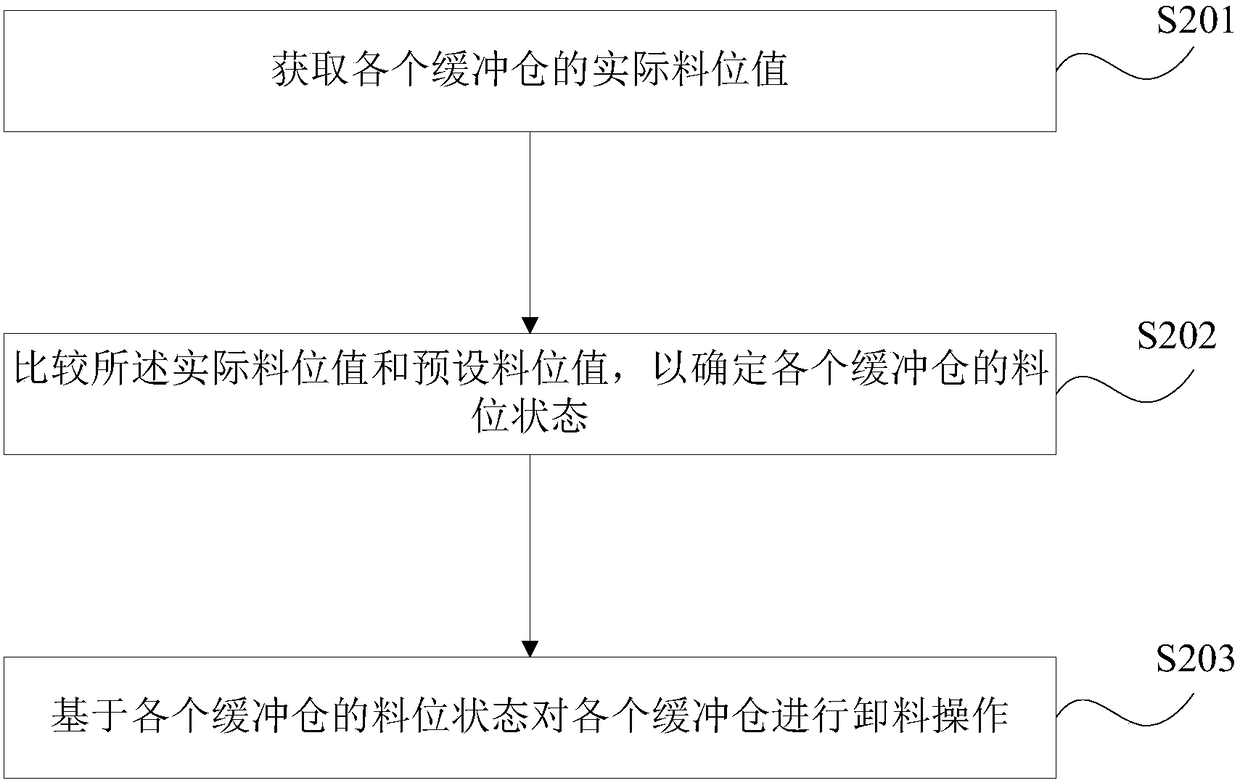
[0065] see figure 2 A schematic flow chart of an automatic uniform unloading method disclosed by an embodiment of the present invention is shown.

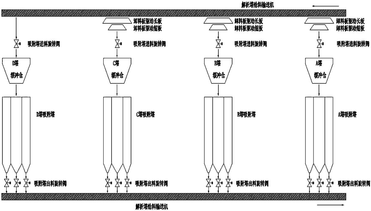
[0066] Depend on figure 1 It can be seen that the method includes:

[0067] S201: Obtain the actual material level value of each buffer bin.

[0068] The actual material level value of each buffer bin is obtained in real time through the material level detector installed inside each buffer bin.

[0069] S202: ...


PUM


Abstract

The invention discloses an automatic uniform discharging control method and device. According to the method, when discharging operation is carried out for buffering bins, material levels of the buffering bins are detected, and actual material values of the buffering bins are obtained, so that the material level state of the buffering bins is determined. When the buffering bins in the low materiallevel state exist, discharging operation is carried out on the buffering bins in the low material level state preferably, and when the buffering bins in the high material level state exist, discharging operation on the buffering bins in the high material level state is prohibited. Compared with the prior art, the discharging sequences of all the buffering bins are adjusted on the basis of the material level state of the buffering bins, the discharging amount of all the buffering bins can be controlled, all the buffering bins can be discharging uniformly, and the buffering bins do not need to be distributed manually again.

Description

technical field [0001] The present application relates to the technical field of flue gas purification, and more specifically, to an automatic discharge control method and device. Background technique [0002] The activated carbon adsorption tower system is one of the most critical links in the entire flue gas purification system for desulfurization, denitrification, dioxin removal, heavy metal removal, dust removal and other trace harmful flue gas components. see figure 1 A schematic structural diagram of an adsorption tower system is shown. The adsorption tower system generally consists of multiple adsorption towers and multiple buffer bins, and each adsorption tower corresponds to a buffer bin. How to uniformly unload the material (activated carbon) into the buffer bin of the adsorption tower is the most complicated, tedious, and energy-intensive link for system operators. System operators must always pay attention to whether the level of activated carbon in the buffer ...

Claims


Application Information

Patent Timeline
IPC IPC(8): B65G65/00
CPCB65G65/005B65G2201/04
Inventor 谢智星李俊杰袁立新
Owner ZHONGYE-CHANGTIAN INT ENG CO LTD
Why Eureka
Try Eureka