Displacement-crawler-type pipe dredging robot

A crawler and robot technology, applied to tracked vehicles, motor vehicles, waterway systems, etc., can solve the problems of high difficulty in dredging, heavy manual workload, and low dredging efficiency, and achieve simple and reliable structure, high mechanical efficiency, Improve the effect of system energy saving

Pending Publication Date: 2018-11-23
CHINA UNIV OF GEOSCIENCES (WUHAN)
0 Cites 15 Cited by

AI-Extracted Technical Summary

Problems solved by technology

But all have great disadvantages, such as large manual workload, ...

Abstract

The invention provides a displacement-crawler-type pipe dredging robot. The displacement-crawler-type pipe dredging robot comprises a dredging reamer mechanism, a displacement-type crawler chassis anda hydraulic mechanism, wherein the dredging reamer mechanism comprises a reamer and a first hydraulic motor which are rotationally connected; the displacement-type crawler chassis comprises two walking crawlers which are oppositely arranged and a crawler support, the walking crawlers comprise crawlers, driving wheels and guiding wheels, the crawlers surround the driving wheels and the guiding wheels, the driving wheels are rotationally connected with a second hydraulic motor, the crawler support comprises a beam hinged to the upper ends of the two guiding wheels and a longitudinal beam provided with slanting adjusting hydraulic cylinders, and the two ends of the slanting adjusting hydraulic cylinders are hinged to the lower ends of the longitudinal beam and the guiding wheels; the hydraulic mechanism comprises a hydraulic oil tank, a variable pump and a multi-way valve which are sequentially connected through a pipe, the variable pump is rotationally connected with a motor, the motordrives the variable pump to suck hydraulic oil in the hydraulic oil tank to the multi-way valve, and the hydraulic oil flows to the first hydraulic motor, the second hydraulic motor and the two slanting adjusting hydraulic cylinders through dividing. The displacement-crawler-type pipe dredging robot has the advantages that the displacement-type crawler chassis is adopted, slant angles of the walking crawlers can be adjusted, and the displacement-crawler-type pipe dredging robot is suitable for cleaning of pipes with different pipe parameters.

Application Domain

Technology Topic

Image

  • Displacement-crawler-type pipe dredging robot
  • Displacement-crawler-type pipe dredging robot
  • Displacement-crawler-type pipe dredging robot

Examples

  • Experimental program(1)

Example Embodiment

[0024] In order to make the objectives, technical solutions, and advantages of the present invention clearer, the following further describes the embodiments of the present invention with reference to the accompanying drawings.
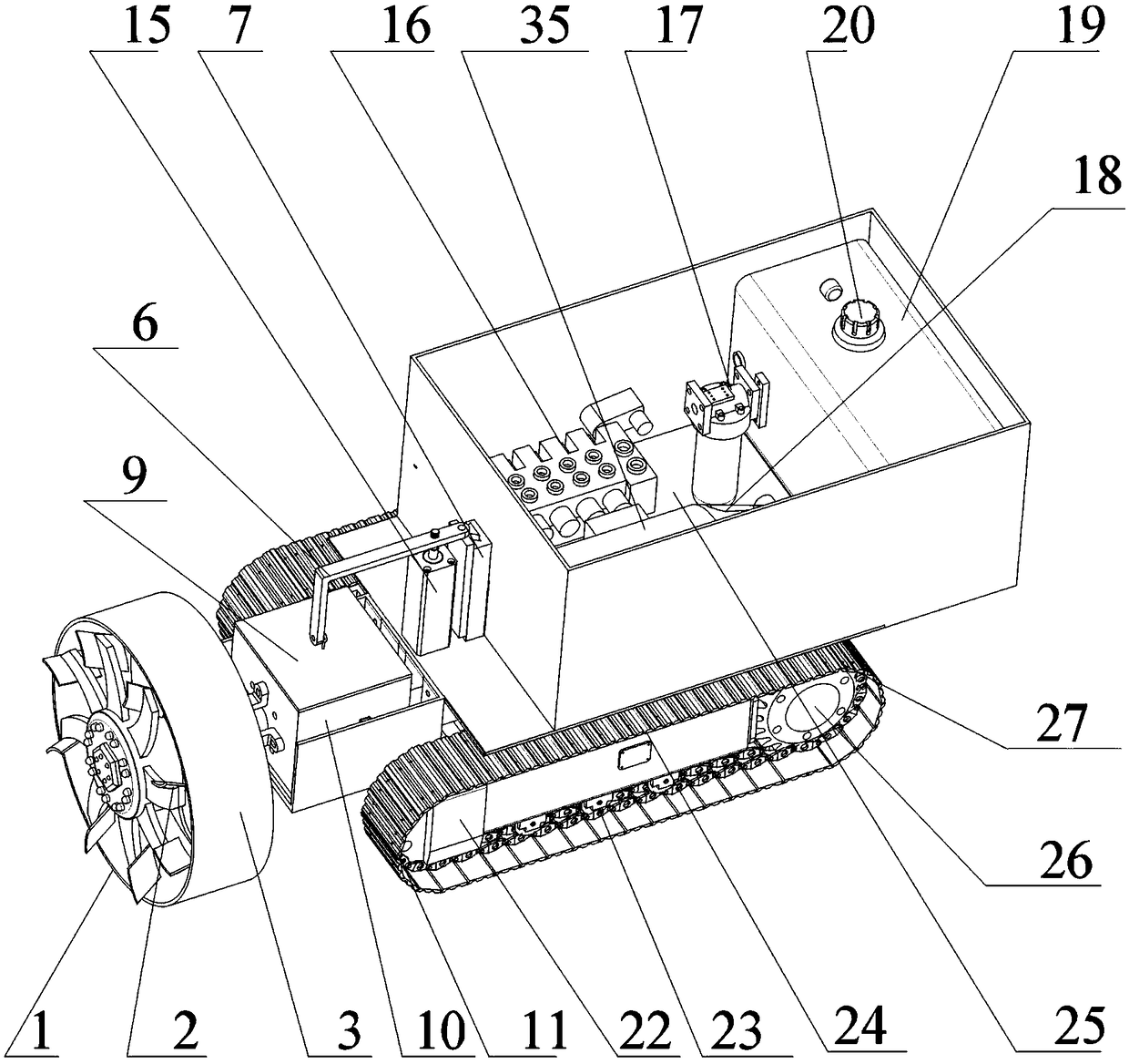
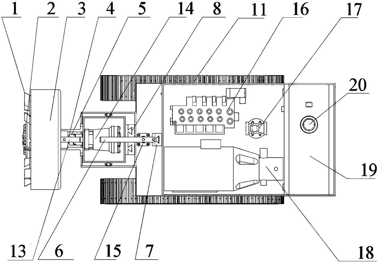
[0025] Please refer to Figure 1 ~ Figure 3 , The embodiment of the present invention provides a displacement crawler pipeline dredging robot, the robot is designed in the form of a carrier vehicle, including: a dredging reamer mechanism that acts on the wall of the drainage pipe 1. A reamer lifting mechanism 9 at the position of the dredging reamer mechanism, a displacement crawler chassis that can adjust the inclination angle of the crawler, and a hydraulic mechanism 25 that provides power for the robot.
[0026] The dredging reamer mechanism 1 is arranged at the front end of the vehicle body. The dredging reamer mechanism 1 includes a reamer 2, a circular bucket 3 and a first hydraulic motor 14. The first hydraulic motor is a BMR hydraulic motor. The reamer 2 includes a cutter shaft 4 and a plurality of cutter bars. The outer end of each cutter bar is connected with a blade, the inner end is fixed on the cutter shaft 4, and all the blades are evenly distributed on the cutter shaft in a ring shape. 4 Peripheral, the blade and the knife bar form an included angle of 30°, the reamer is arranged in the circular bucket 3, and the reamer 2 and the circular bucket 3 are coaxial, The rear end of the knife shaft 4 passes through the circular bucket 3 and is rotatably connected to the output shaft 13 of the first hydraulic motor through a coupling 5. The first hydraulic motor 14 and the circular bucket 3 Both are fixedly connected with the reamer lifting mechanism.
[0027] The rear end of the dredging reamer mechanism 1 is connected to the reamer lifting mechanism 9. The reamer lifting mechanism 9 includes a motor box 10, a lifting hydraulic cylinder 15 and a boom 6, and the lifting hydraulic cylinder 15 is LA thin A hydraulic cylinder, the first hydraulic motor 14 is fixed in the motor box 10, and the rear end of the circular bucket 3 is fixed to the front outer wall of the motor box 10, and the boom 6 is an L-shaped boom, One end is fixedly connected to the upper part of the motor box 10, and the other end is fixedly connected to the lifting hydraulic cylinder 15 and this end is also provided with a sliding block. The rear side of the lifting hydraulic cylinder 15 is also provided with a boom sliding rail 7. When the cylinder 15 moves up and down, the motor box 10 is driven up and down, and the slider slides in the hanger rail 7 to prevent the hanger 6 from shifting, thereby ensuring the adjustment of the position of the reamer 2.
[0028] The displacement type crawler chassis is arranged at the bottom of the vehicle body, and the displacement type crawler chassis includes two walking crawlers 24 and a crawler support 33 arranged oppositely. Two support blocks 34 are fixed on the upper part of the crawler support 33. The box is fixed on the two supporting blocks 34, each of the walking crawlers 24 includes a crawler, a driving wheel 26, a guide wheel 22, and a plurality of supporting wheels 23. The crawler includes a crawler chassis 28 and a crawler chain 27, The crawler chain piece 27 is arranged inside the crawler chassis 28, and the crawler belt is in a tensioned state while surrounding the driving wheel 26 and the guide wheel 22 and relies on the crawler chain piece 27 to engage with both, so The guide wheel 22 is used as the front wheel of the walking crawler 24, the driving wheel is used as the rear wheel of the walking crawler 24, and all the supporting wheels 23 are arranged between the driving wheel 26 and the guide wheel 22 and are uniform. It meshes with the crawler chain pieces of the walking crawler 24, the driving wheel 26 is rotatably connected to the second hydraulic motor, the crawler support 33 is located between the two walking crawlers 24, and the crawler support 33 includes horizontal beams connected to each other And a vertical longitudinal beam, both ends of the beam are provided with first pin holes 31, the longitudinal beam is provided with a second pin hole, the upper and lower parts of the guide wheel are both provided with a support 30 and the support 30 is provided with hinge holes 29, the two first pin holes 32 are aligned with the hinge holes 29 on the upper part of the two guide wheels 22, and are connected with the first pin shaft 31, so that the two ends of the beam are connected to the two guide The upper end of the wheel 22 is hinged. Both sides of the longitudinal beam are provided with a tilt adjusting hydraulic cylinder 21. The tilt adjusting hydraulic cylinder 21 is an HSG hydraulic cylinder. Both ends of the tilt adjusting hydraulic cylinder 21 are provided with rotating holes. The rotation hole at the upper end of the tilt adjusting hydraulic cylinder 21 is aligned with the second pin hole provided on the longitudinal beam and connected with the second pin, and the rotation hole at the lower end is aligned with the second pin hole and connected with the third pin, Therefore, both ends of the tilt adjusting hydraulic cylinder 21 are pivotally hinged to the longitudinal beam and the lower end of the guide wheel 22 respectively.
[0029] In the box 12 above the vehicle body of the hydraulic mechanism 25, a base 11 is provided on the upper part of the displacement type crawler chassis. The box 12 is fixed on the base 11, the first hydraulic motor 14 and the The suspension rod 6 slide rail is fixed on the base 11, the front end of the base 11 is fixed with a motor box groove, the motor box 10 is supported in the motor box groove, and the rear surface of the motor box groove is provided with a motor box slide The motor box 10 can slide up and down along the motor box slide rail 8. The hydraulic mechanism 25 includes a hydraulic oil tank 19, a variable pump 18 and a multi-way valve 16 connected by pipes in sequence. The hydraulic oil tank 19 is provided with There are a filter 17 and an oil tank port 20. The output end of the filter 17 is connected to the variable pump 18, the filter 17 is a ZU-H filter, and the variable pump 18 is A10 variable plunger pump. The multi-way valve 16 uses the M7-LUDV multi-way valve. The multi-way valve 16 is connected to the first hydraulic motor 14, the lifting hydraulic cylinder 15, the second hydraulic motor and the two tilting hydraulic cylinders respectively. 21. The variable pump 18 and the motor 35 are rotatably connected, and the motor 35 drives the variable pump 18 to suck the hydraulic oil in the hydraulic oil tank 19 to the multi-way valve 16, the multi-way valve 16 The hydraulic oil is diverted to the first hydraulic motor 14 to drive the reamer 2 to rotate, to the lifting hydraulic cylinder 15 to lift the boom 6 up and down to adjust the position of the reamer 2, To the second hydraulic motor is used to drive the driving wheel 26 to rotate, and to the two tilt adjustment hydraulic cylinders 21 are used to make the tilt adjustment hydraulic cylinder 21 push outwards or pull inward the connected drive wheels 26 The upper ends of the two walking crawlers 24 are connected by the crossbeam to a fixed width. The tilt hydraulic cylinder 21 pushes or pulls the walking crawler to tilt inward and outward to change the width of the lower end of the walking crawler 24, so that the walking The crawler belt 24 is inclined 0-20° inwardly or outwardly.
[0030] In this article, the directional terms such as front, back, upper, lower, etc. are defined in terms of the parts in the drawings and the positions between the parts in the drawings, just to express the technical solution clearly and conveniently. It should be understood that the use of the location words should not limit the scope of protection claimed in this application.
[0031] In the case of no conflict, the above-mentioned embodiments and the features in the embodiments herein can be combined with each other.
[0032] The above descriptions are only preferred embodiments of the present invention and are not intended to limit the present invention. Any modification, equivalent replacement, improvement, etc. made within the spirit and principle of the present invention shall be included in the protection of the present invention. Within range.

PUM

no PUM

Description & Claims & Application Information

We can also present the details of the Description, Claims and Application information to help users get a comprehensive understanding of the technical details of the patent, such as background art, summary of invention, brief description of drawings, description of embodiments, and other original content. On the other hand, users can also determine the specific scope of protection of the technology through the list of claims; as well as understand the changes in the life cycle of the technology with the presentation of the patent timeline. Login to view more.

Similar technology patents

Suction base for intelligent nursing toilet bowl

ActiveCN104382519AReliable structureAutomatically adjusts for comfortBathroom accessoriesTraffic volumeSpray nozzle
Owner:CRRC SHANDONG CO LTD

Classification and recommendation of technical efficacy words

  • Reliable structure
  • Reasonable design

Ground microgravity dynamic loading simulation mechanism for satellite

Owner:SHENYANG INST OF AUTOMATION - CHINESE ACAD OF SCI

Construction method of bilateral biased small-clear distance tunnel

InactiveCN102128035AReasonable designThe construction steps are arranged compactlyUnderground chambersTunnel liningClerestoryEnvironmental geology
Owner:CHONGQING UNIV
Why Eureka
Try Eureka