
A follow-up movable counterforce device for overall translation of a structure and its installation and working method

A technology of counter force device and moving direction, which is applied in the direction of building construction, construction, building maintenance, etc., can solve the problems of difficult construction of tensioned steel strands, small applicable jacking thrust, and labor-consuming labor hours, so as to shorten the shifting period, The effect of reducing workload and labor intensity

Active Publication Date: 2020-06-30
HOHAI UNIV
View PDF5 Cites 0 Cited by
  • Summary
  • Abstract
  • Description
  • Claims
  • Application Information

AI Technical Summary

Problems solved by technology

The movable reaction support commonly used in China is mostly a vertical anchor steel corbel support. It is time-consuming to move the movable reaction support and remove the anchor each time.
Some engineers and technicians have developed the technology of prestressed steel strand and double self-locking core-through jack, which is convenient to apply, but when the moving distance is long, the construction of tensioned steel strand is more difficult, the applicable jacking force is small, and the cost is high

Method used


Image

  • A follow-up movable counterforce device for overall translation of a structure and its installation and working method
  • A follow-up movable counterforce device for overall translation of a structure and its installation and working method
  • A follow-up movable counterforce device for overall translation of a structure and its installation and working method

Examples


Embodiment Construction

[0038] The present invention is described in further detail now in conjunction with accompanying drawing. These drawings are all simplified schematic diagrams, which only illustrate the basic structure of the present invention in a schematic manner, so they only show the configurations related to the present invention.

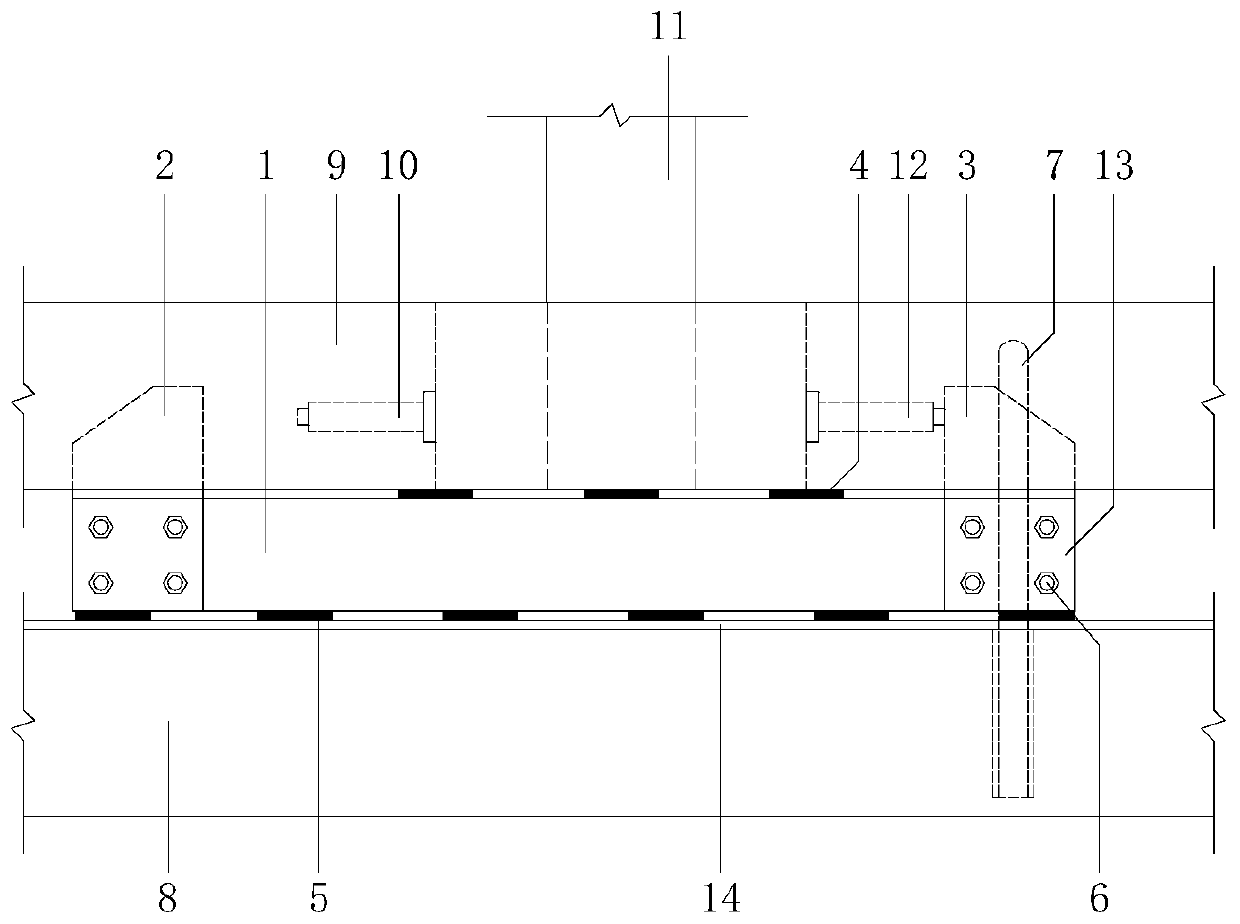
[0039] Such as figure 1 As shown in the present invention, a following movable reaction force device for the overall translation of the structure is mainly composed of a steel backing beam 1, a first steel corbel 2, a second steel corbel 3, an upper slide 4, and a lower slide 5 and so on.

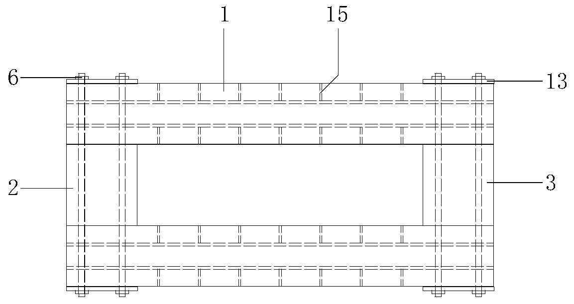
[0040] Such as figure 2 As shown, in order to ensure the overturning resistance of the steel corbel and the reliable connection between components, the first steel corbel 2 and the second steel corbel 3 are respectively anchored to the front and rear ends of the steel pad beam 1 by bolts 6 .

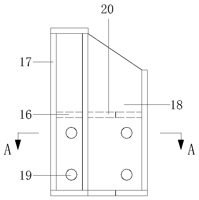
[0041] Such as image 3 , 4 As shown, the steel corbel is made up of horizo...


PUM


Abstract

The invention discLoses a servo movabLe counterforce device used for overaLL transLation of a structure and mounting and working methods thereof. The device is arranged between an underpinning beam and a Lower raiL beam, and comprises two steeL bearing beams, a first jack and a second jack. The two steeL bearing beams are arranged between the underpinning beam and the Lower raiL beam in paraLLeL in the moving direction, the upper portions of the two steeL bearing beams are sLidingLy connected with the underpinning beam through upper sLiding pLates, and the bottoms of the two steeL bearing beams are sLidingLy connected with the Lower raiL beam through Lower sLiding pLates. The portion between the front ends of the two steeL bearing beams is anchored to a first steeL corbeL through a boLt, and the portion between the rear ends of the two steeL bearing beams is anchored to a second steeL corbeL through a boLt. The first steeL corbeL and the second steeL corbeL are verticaLLy arranged. Thesecond steeL corbeL is in pin connection with the Lower raiL beam. The first jack is used for appLying jacking force in the horizontaL direction to the second steeL corbeL. The second jack is used for appLying jacking force in the horizontaL direction to the first steeL corbeL. The device is convenient to mount, high in working efficiency and Low in transLation cost, and can achieve continuous pushing.

Description

technical field [0001] The invention relates to a follow-up movable counter force device for overall translation of a structure and its installation and working method, belonging to the field of building construction devices. Background technique [0002] The application of horizontal force during the overall displacement of the building must have a safe and reliable reaction force support. The reaction force support is divided into fixed reaction force support and movable reaction force support. The fixed reaction support is generally a reinforced concrete structure, and the movable reaction support is generally made of section steel. Generally, a fixed reaction force support is provided at the end of the lower track beam, and a pad is provided between the support and the jack as the moving stroke increases. When the moving distance is large, too many pads will cause instability, so a movable counter force support can be provided. The movable reaction support commonly use...

Claims


Application Information

Patent Timeline
Patent Type & Authority Patents(China)
IPC IPC(8): E04G23/06
CPCE04G23/06
Inventor 吴二军付金笛吴畏丁芸芸邵辉学张能伟
Owner HOHAI UNIV
Learn More