
Double layer erecting ring of partially prestressed concrete electrical pole and application thereof

A technology of erecting rings and prestressing, applied in the field of electric poles, can solve the problems of easily falling off main bars, non-vertical, affecting the inherent quality of concrete poles, etc., and achieve the effect of safe and reliable structure, good toughness and crack resistance.

Inactive Publication Date: 2018-11-23
儋州宇顺实业有限公司
View PDF6 Cites 1 Cited by
  • Summary
  • Abstract
  • Description
  • Claims
  • Application Information

AI Technical Summary

Problems solved by technology

[0002] At present, the control of the protective layer of electric poles is a difficult problem for many manufacturers. Most domestic manufacturers use plastic rings to support the distance between the main reinforcement and the inner wall of the steel mold to achieve the control of the protective layer. This method is not suitable for high-strength poles densely covered with steel bars. Cage, since the plastic ring is round, with a diameter of about 45mm, there is no extra place to place the plastic ring in the high-strength rod dense reinforcement cage, and the plastic ring is easy to fall off or not perpendicular to the main reinforcement during the tensioning process, so use It is difficult for the plastic ring to control the protective layer of the pole, and it is easy to break the pole at the position of the rubber ring under the condition of the pole being subjected to lateral force, and some manufacturers use a single-layer vertical ring, which can be easily damaged during the handling and tensioning process. The vertical ring of the middle frame is easy to crooked, the main reinforcement is not vertical, and the steel cage is not round, which affects the internal quality of the concrete pole

Method used


Image

  • Double layer erecting ring of partially prestressed concrete electrical pole and application thereof
  • Double layer erecting ring of partially prestressed concrete electrical pole and application thereof
  • Double layer erecting ring of partially prestressed concrete electrical pole and application thereof

Examples


Embodiment Construction

[0019] In describing the present invention, it should be understood that the terms "center", "longitudinal", "transverse", "upper", "lower", "front", "rear", "left", "right", " The orientations or positional relationships indicated by "vertical", "horizontal", "top", "bottom", "inner" and "outer" are based on the orientations or positional relationships shown in the drawings, and are only for the convenience of describing the present invention and Simplified descriptions, rather than indicating or implying that the device or element referred to must have a particular orientation, be constructed and operate in a particular orientation, and thus should not be construed as limiting the invention. In addition, the terms "first", "second", etc. are used for descriptive purposes only, and should not be interpreted as indicating or implying relative importance or implicitly specifying the quantity of the indicated technical features. Thus, a feature defined as "first", "second", etc....


PUM


Abstract

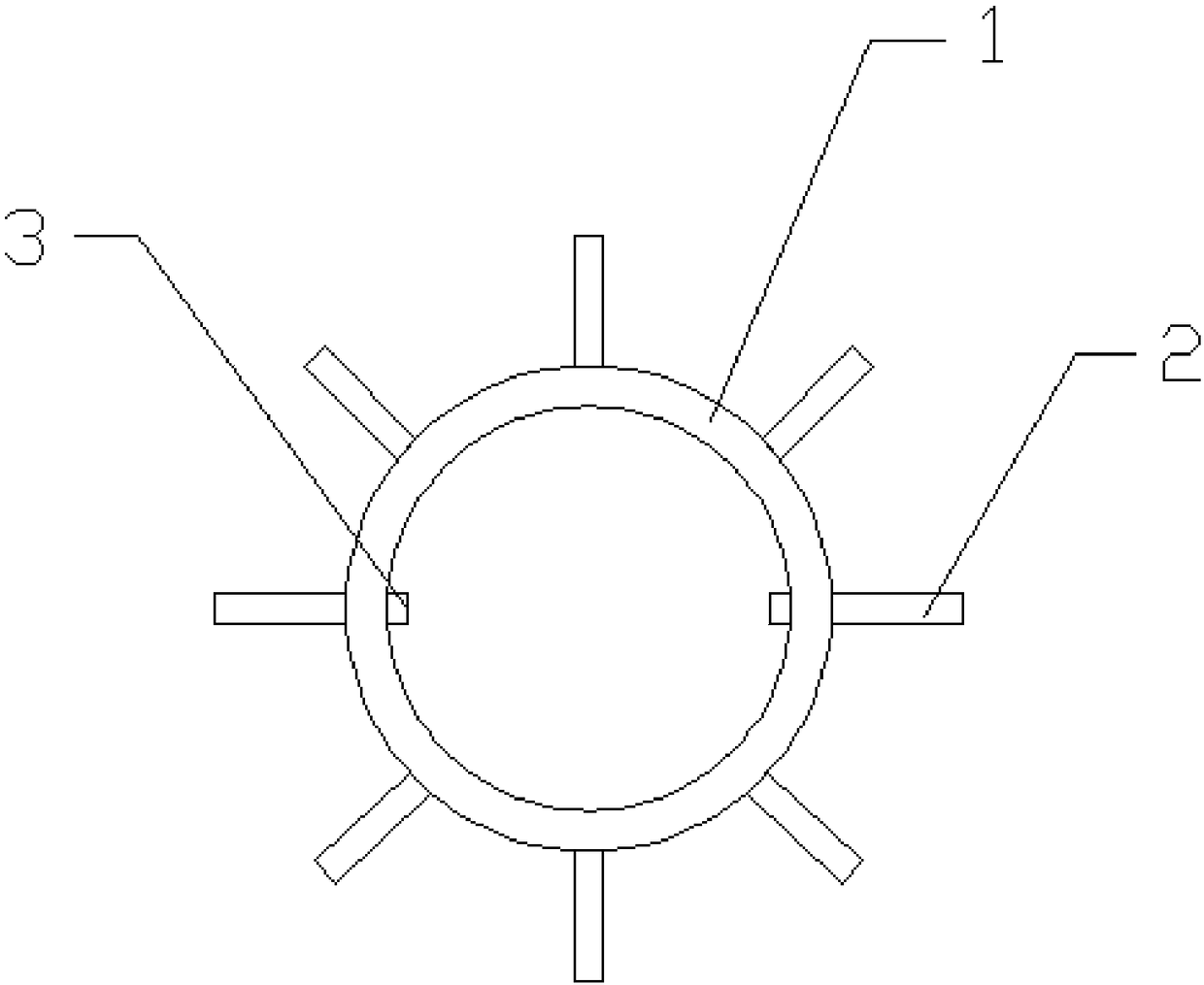
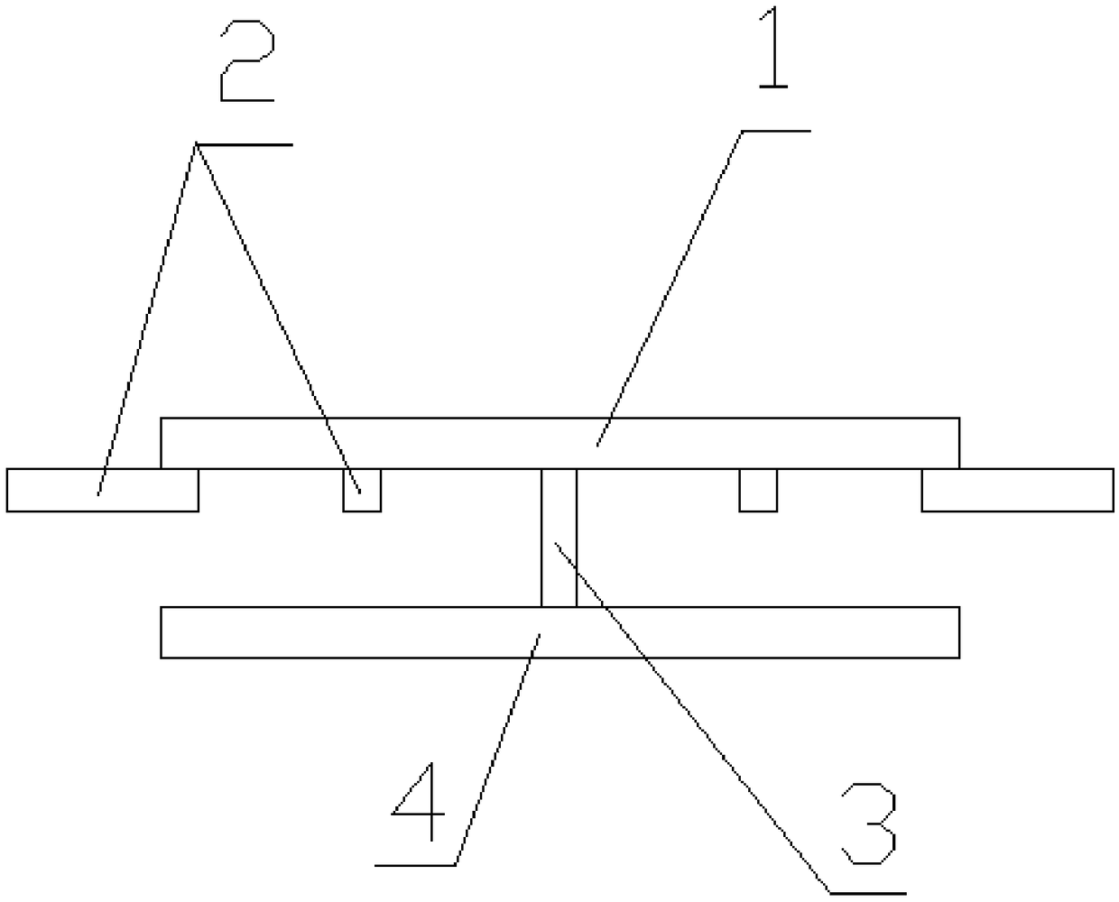
The invention discloses a double layer erecting ring for a partially prestressed concrete electrical pole. The ring comprises an erecting ring body (1), positioning rods (2), a connecting rod (3) andan auxiliary ring (4), the erecting ring body (1) is parallel to the auxiliary ring (4), the erecting ring body (1) and the auxiliary ring (4) are fixedly connected by the connecting rod (3), and a plurality of positioning rods (2) are horizontally arranged on the erecting ring body (1). The ring has the advantages of both structures of the prestressed concrete electrical pole and ordinary concrete, has better toughness and crack resistance, better controls cracks, deformation and damage under the use conditions, and is safe and reliable in the structure.

Description

technical field [0001] The invention relates to the technical field of electric poles, in particular to a partially prestressed concrete electric pole double-layer stand ring and its application. Background technique [0002] At present, the control of the protective layer of electric poles is a difficult problem for many manufacturers. Most domestic manufacturers use plastic rings to support the distance between the main reinforcement and the inner wall of the steel mold to achieve the control of the protective layer. This method is not suitable for high-strength poles densely covered with steel bars. Cage, since the plastic ring is round, with a diameter of about 45mm, there is no extra place to place the plastic ring in the high-strength rod dense reinforcement cage, and the plastic ring is easy to fall off or not perpendicular to the main reinforcement during the tensioning process, so use It is difficult for the plastic ring to control the protective layer of the pole, ...

Claims


Application Information

Patent Timeline
Patent Type & Authority Applications(China)
IPC IPC(8): E04H12/12
CPCE04H12/12
Inventor 陈洋黄朝俊
Owner 儋州宇顺实业有限公司
Learn More