Super apochromatic supersurface composite microlens

An apochromatic and micro-lens technology, applied in the optical field, can solve the problems of sacrificing bandwidth and numerical aperture, correcting complex optical systems such as chromatic aberration, and achieving the effect of simple structure, elimination of chromatic aberration, and reduction of bandwidth.

Active Publication Date: 2018-11-23
UNIV OF SHANGHAI FOR SCI & TECH
View PDF2 Cites 17 Cited by
  • Summary
  • Abstract
  • Description
  • Claims
  • Application Information

AI Technical Summary

Benefits of technology

This patented technology improves upon existing designs that use multiple layers or special materials to achieve specific functions such as high resolution imagery (HRI) systems. By optimizing the arrangement of different components within each layer, this new method allows for more efficient transmissions over longer distances without increasing their size. Additionally, due to its simplified construction, there are fewer parts needed than previous methods while still maintaining good image quality at larger sizes. Overall, these improvements improve performance and reduce bulkiness compared to current technologies used on HRIs.

Problems solved by technology

Technological Problem: Current methods for reducing color distortion involve adjusting various factors such as thicknesses of layers within the device's substrate layer, depth of penetrations into the device, alignment between multiple components, etc., leading to complexity and difficulty in manufacturing these types of microscopic opticals without sacrificial effects like excessively large dimensions and poor performance.

Method used


Image

  • Super apochromatic supersurface composite microlens
  • Super apochromatic supersurface composite microlens
  • Super apochromatic supersurface composite microlens

Examples


Embodiment 1

[0031] Embodiment 1: Ordinary super-surface composite microlens.

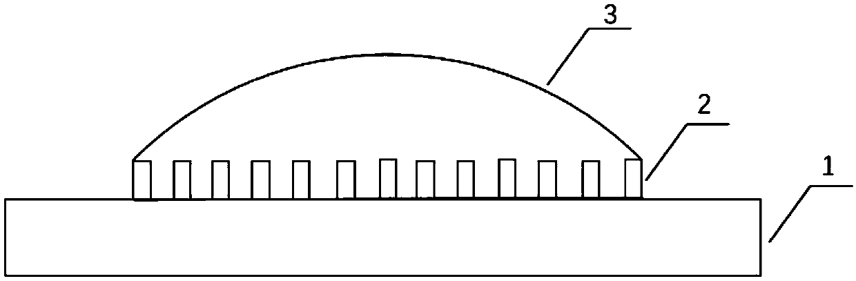
[0032] Such as figure 1 As shown, the structure diagram of a super-apochromatic super-surface composite microlens provided by this embodiment. This embodiment is composed of a first lens and a second lens. The first lens is a positive refractive power metasurface lens, and the second lens is a positive refractive power microlens. Among them, the positive refractive power metasurface lens has negative dispersion properties to produce negative chromatic aberration, and the positive refractive power spherical refractive micro lens has positive dispersion properties to produce positive chromatic aberration. The numerical aperture and positive refractive power spherical surface of the positive refractive power metasurface lens are optimized by numerical simulation software FDTD. The refractive spherical curvature of the refractive lens causes the above two lenses to produce chromatic aberrations of equal magnitude and ...

Embodiment 2

[0040] Embodiment 2: Super-surface composite microlens with partial correction of chromatic aberration.

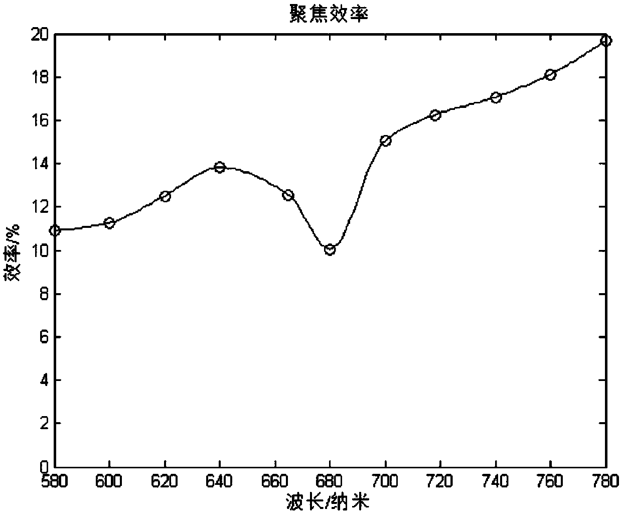
[0041] This embodiment provides a super-apochromatic super-surface composite microlens with partial correction of chromatic aberration. The system aperture size is 50um, the total focal length of the system is 30.3um, the working wavelength range is 580nm-780nm, and the numerical aperture (NA) is 0.635. It can achieve achromatic aberration focusing within the working wavelength range, and the secondary spectrum is less than 1um. The structure diagram is as Image 6 Shown.

[0042] For the present invention, if the negative chromatic aberration produced by the first lens exceeds the chromatic aberration compensation ability produced by the second lens, the nano-antenna array of the first lens itself can be designed to partially correct the chromatic aberration structure, which can also achieve high system values There is no chromatic aberration focusing under the aperture.

[00...


PUM

PropertyMeasurementUnit
Center heightaaaaaaaaaa
Wavelengthaaaaaaaaaa
Focal lengthaaaaaaaaaa

Abstract

The invention discloses a super apochromatic supersurface composite microlens, which comprises a first lens and a second lens, wherein the first lens is a positive-focal power supersurface lens with anegative dispersion property, and the particular structure is a nano-antenna array with a wide spectral response; the second lens is a positive-focal power spherical reflection microlens with a positive dispersion property, and the particular structure is a flat convex spherical microlens; the first lens comprises an upper surface and a lower surface of the nano-antenna array; the second lens comprises a second lens plane side and a second lens curved surface; the lower surface of the first lens is mutually overlapped with the plane side of the second lens; and the nano-antenna array of the first lens is embedded inside the curved surface of the second lens. The technical problems that a complex optical system is needed for chromatic aberration correction of a positive-refractive index material, and the supersurface material needs to sacrifice a bandwidth and a numerical aperture in order to correct the chromatic aberration can be solved, and the super apochromatic supersurface composite microlens has the advantages of simple structure and miniaturization.

Description


Claims


Application Information

Patent Timeline
Owner UNIV OF SHANGHAI FOR SCI & TECH
Why Eureka
Try Eureka