
Convenient-to-assemble efficient heat-dissipating bus duct

A heat-dissipating, busway technology, applied in the field of busway, can solve the problems of reducing the service life of the busway, unable to meet the requirements of expansion and contraction, and the degree of freedom of installation cannot be adjusted, so as to ensure the safety of use, the elimination of bad vibration, and the absence of mechanical The effect of vibration

Inactive Publication Date: 2018-11-23
江苏雄海智能电气有限公司
View PDF10 Cites 1 Cited by
  • Summary
  • Abstract
  • Description
  • Claims
  • Application Information

AI Technical Summary

Problems solved by technology

[0002] In the prior art: the patent of authorized publication number CN 206992645 U discloses a high-efficiency heat-dissipating busway that is easy to assemble, including a shell, the top of the shell is provided with a cover plate, and a locking piece is fixedly connected between the shell and the cover plate , the middle part of the outer surface of the shell is fixedly installed with a raised block, the two sides of the inner cavity of the cover plate are fixedly installed with a limit block, one side of the limit block is fixedly connected with a second spring, and one end of the second spring is fixedly connected with a second connection One side of the second connecting rod is fixedly installed with a clamping rod, and its installation freedom cannot be adjusted, which cannot meet the expansion and contraction requirements caused by different temperature drops and thermal expansion and contraction. At the same time, it does not have shock absorption capacity. The generated mechanical vibration and seismic waves are likely to cause damage to the closed busbar, thereby reducing the service life of the busway. It adopts the exhaust fan for heat dissipation, which will generate mechanical vibration and consume energy, resulting in poor working stability of the busway

Method used


Image

  • Convenient-to-assemble efficient heat-dissipating bus duct
  • Convenient-to-assemble efficient heat-dissipating bus duct
  • Convenient-to-assemble efficient heat-dissipating bus duct

Examples


Embodiment Construction

[0019] The following will clearly and completely describe the technical solutions in the embodiments of the present invention with reference to the accompanying drawings in the embodiments of the present invention. Obviously, the described embodiments are only some, not all, embodiments of the present invention. Based on the embodiments of the present invention, all other embodiments obtained by persons of ordinary skill in the art without making creative efforts belong to the protection scope of the present invention.

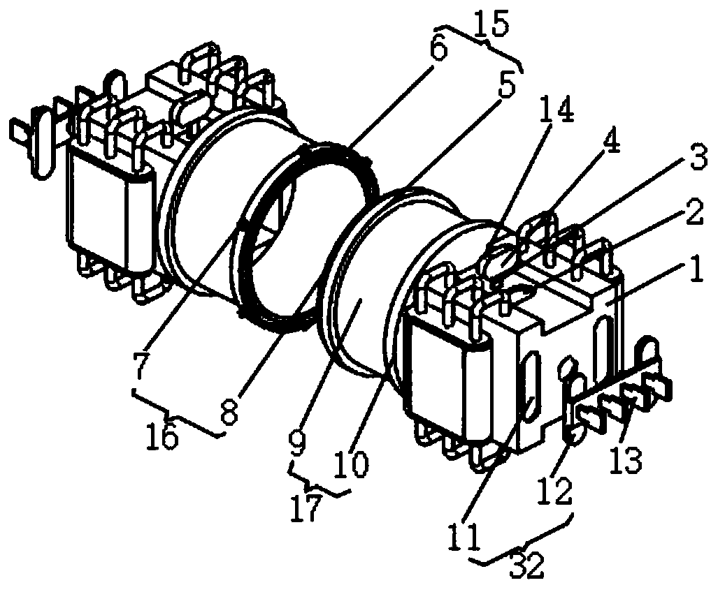
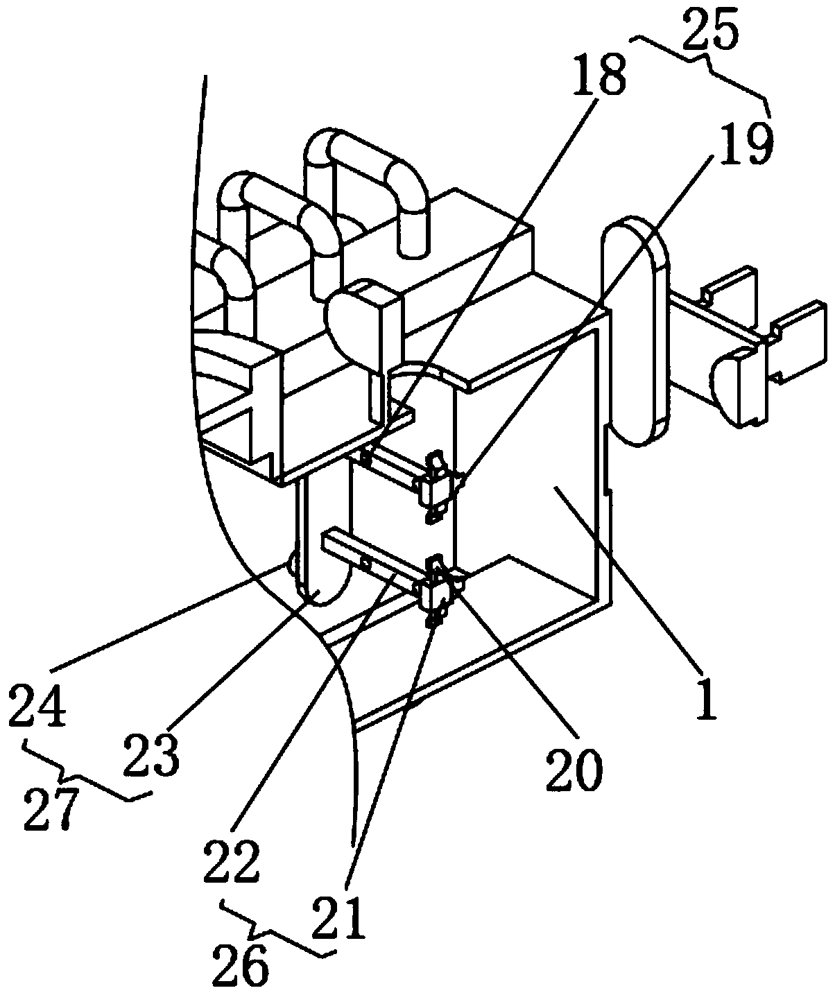
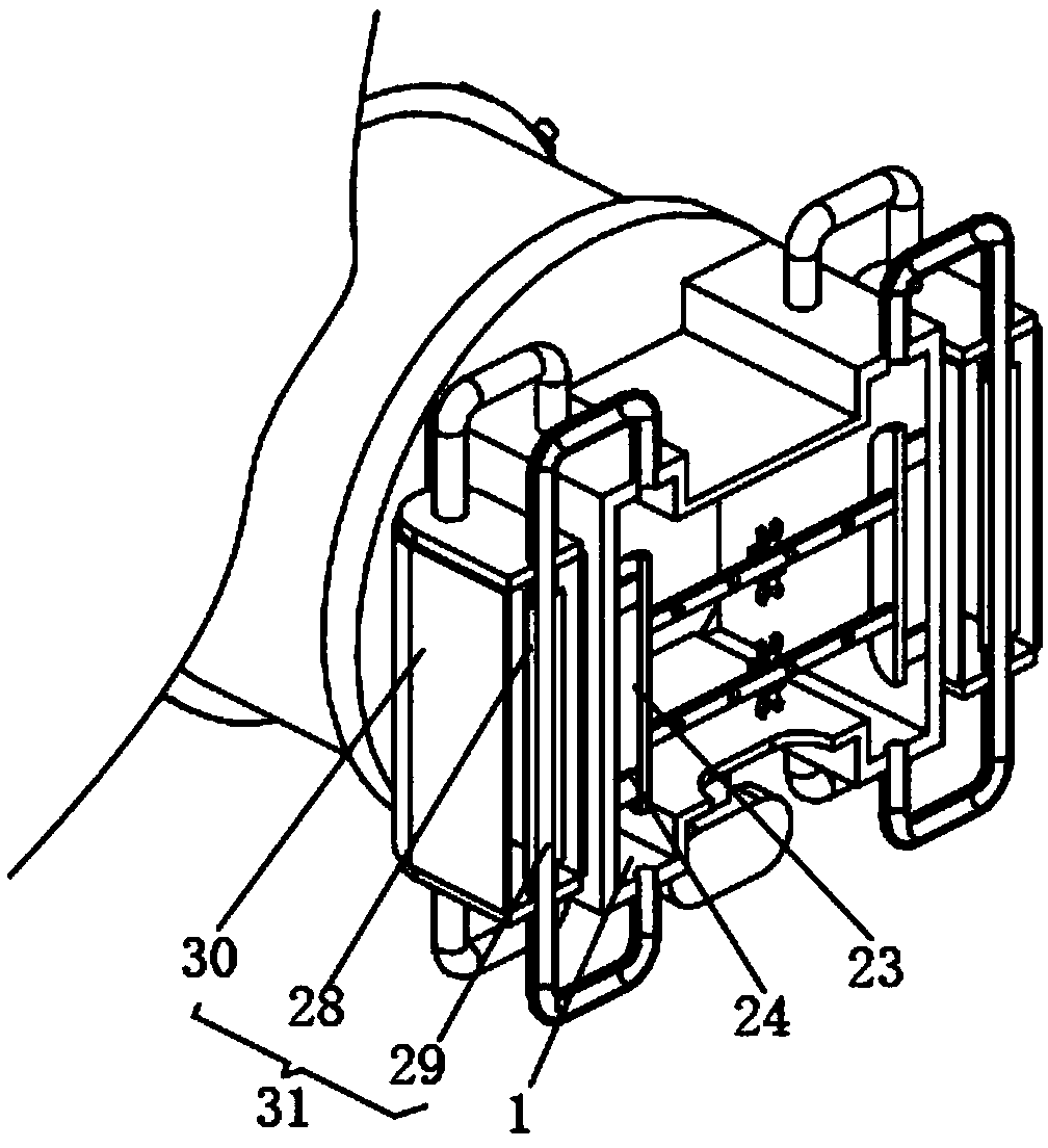
[0020] see Figure 1-3 , the present invention provides a technical solution: a high-efficiency heat-dissipating busway that is easy to assemble, including a housing 1, and the housing 1 has two groups, and the two groups of housings 1 are symmetrically arranged left and right, and the ends of the housing 1 are equipped with The adjustment mechanism 17, the two sets of adjustment mechanisms 17 are connected by the first clamping mechanism 15, and the first cla...


PUM


Abstract

The invention discloses a convenient-to-assemble efficient heat-dissipating bus duct, which comprises two groups of shells, wherein the two groups of shells are bilaterally symmetrically arranged; adjustment mechanisms are arranged at the end parts of the shells; two groups of adjustment mechanisms are connected through a first clamping mechanism; and the first clamping mechanism is fixed througha locking mechanism. According to the convenient-to-assemble efficient heat-dissipating bus duct, the mounting freedom of the shells is adjusted through the adjustment mechanisms, so that the convenient-to-assemble efficient heat-dissipating bus duct is good in flexibility and convenient to meet different mounting requirements, can meet different temperature drops and the telescoping requirement caused by thermal expansion and cold contraction and also can compensate an error caused by foundation settlement; two groups of shells are assembled through the first clamping mechanism, so that the convenient-to-assemble efficient heat-dissipating bus duct is convenient to mount and remove and the assembly efficiency is greatly improved; and the first clamping mechanism is fixed through the locking mechanism, so that connection positions of two groups of bus ducts are prevented from being loosened and the use safety of the bus duct is ensured.

Description

technical field [0001] The invention relates to the technical field of bus ducts, in particular to an efficient and heat-dissipating bus duct that is easy to assemble. Background technique [0002] In the prior art: the patent of authorized publication number CN 206992645 U discloses a high-efficiency heat-dissipating busway that is easy to assemble, including a shell, the top of the shell is provided with a cover plate, and a locking piece is fixedly connected between the shell and the cover plate , the middle part of the outer surface of the shell is fixedly installed with a raised block, the two sides of the inner cavity of the cover plate are fixedly installed with a limit block, one side of the limit block is fixedly connected with a second spring, and one end of the second spring is fixedly connected with a second connection One side of the second connecting rod is fixedly installed with a clamping rod, and its installation freedom cannot be adjusted, which cannot meet...

Claims


Application Information

Patent Timeline
IPC IPC(8): H02G5/06H02G5/10F16F15/02
Inventor 顾大伟孙延锋马高松
Owner 江苏雄海智能电气有限公司
Learn More