Power supply system and power supply system starting method

A technology of power supply system and power electronics, applied in the direction of electrical components, circuit devices, AC network circuits, etc., can solve the problems that AC transformers cannot adapt to energy usage scenarios, poor flexibility of power distribution, and singleness

Pending Publication Date: 2018-11-23
GUANGDONG POWER GRID CO LTD +1
View PDF7 Cites 9 Cited by
  • Summary
  • Abstract
  • Description
  • Claims
  • Application Information

AI Technical Summary

Problems solved by technology

[0003] At present, in the traditional AC distribution network, the problems of high AC-DC energy conversion loss, poor power distribution flexibility, and low matching of power distribution links have become increasingly prominent. In some places with limited locations, it is difficult to install AC transformers.
With the rapid development of the national economy, the application fields of DC power supply equipment are becoming wider and wider, and the demand for AC-DC hybrid power supply is increasing. At present, the AC transformer with a single energy conversion cannot adapt to n

Method used


Image

  • Power supply system and power supply system starting method
  • Power supply system and power supply system starting method
  • Power supply system and power supply system starting method

Examples


Embodiment 1

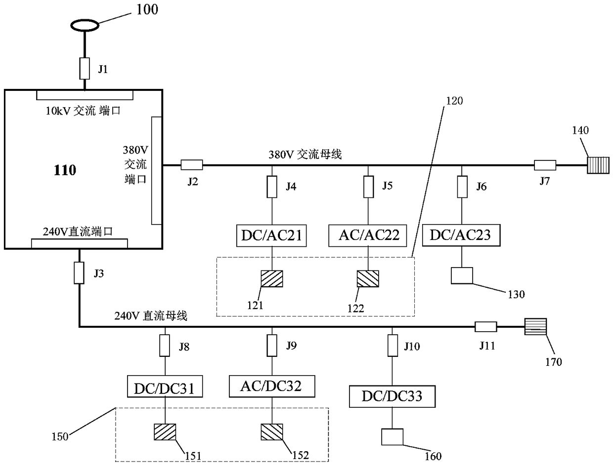
[0049] This embodiment provides a power supply system, such as figure 1 As shown, the power supply system includes: a three-port power electronic transformer 110, a first renewable energy system 120, a first energy storage system 130, a second renewable energy system 150, and a second energy storage system 160;

[0050] The input end of the three-port power electronic transformer 110 is connected to the high-voltage grid 100;

[0051] Both the first renewable energy system 120 and the first energy storage system 130 are connected to the AC output port of the three-port power electronic transformer 110;

[0052] Both the second renewable energy system 150 and the second energy storage system 160 are connected to the DC output port of the three-port power electronic transformer 110 .

[0053] Wherein, the first renewable energy system 120 includes a first photovoltaic system 121 and a first wind energy system 122; the second renewable energy system 150 includes a second photovo...

Embodiment 2

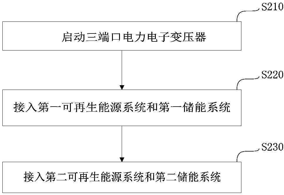
[0060] This embodiment provides a method for starting a power supply system, which is used to start the power supply system provided in Embodiment 1, such as figure 2 As shown, the method includes the following steps:

[0061] Step S210, starting the three-port power electronic transformer;

[0062] Step S220, connecting the first renewable energy system and the first energy storage system;

[0063] Step S230, connecting the second renewable energy system and the second energy storage system.

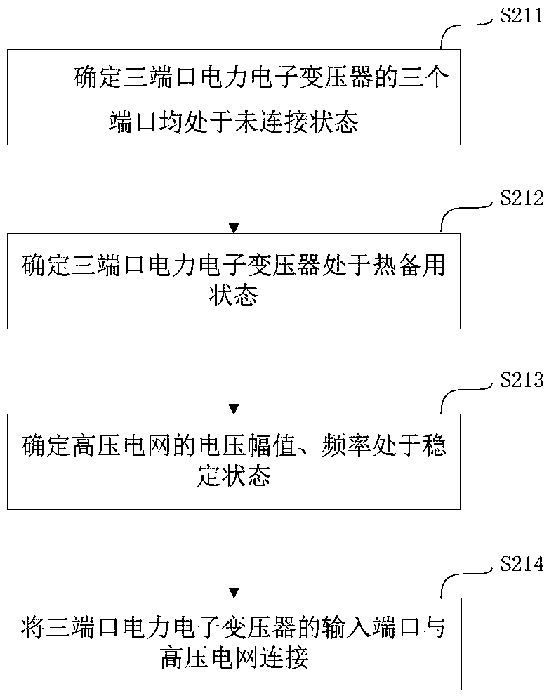
[0064] Specifically, in the method for starting the power supply system, step S210, the process of starting the three-port power electronic transformer is as follows image 3 shown, including:

[0065] Step S211, determining that all three ports of the three-port power electronic transformer are in an unconnected state;

[0066] Step S212, determining that the three-port power electronic transformer is in a hot standby state;

[0067] Step S213, determining that the voltage amplit...


PUM


Abstract

The invention provides a power supply system and a power supply system starting method, and belongs to the technical field of power supply. The power supply system provided by the embodiments of the present invention comprises a three-port power electronic transformer, a first renewable energy system, a first energy storage system, a second renewable energy system and a second energy storage system; the input end of the three-port power electronic transformer is connected with the high-voltage power grid; the first renewable energy system and the first energy storage system are both connectedwith the alternating current output port of the three-port power electronic transformer; the second renewable energy system and the second energy storage system are both connected with the direct current output port of the three-port power electronic transformer, and the AC/DC distribution, the renewable energy system and the energy storage system are integrated into a power supply system to provide power distribution for the user, so that the economical efficiency, the reliability and the flexibility of user electricity utilization are realized.

Description

technical field [0001] The present invention relates to the technical field of power supply, in particular to a power supply system and a method for starting the power supply system. Background technique [0002] Electricity is the source of power for the development of the national economy and provides a reliable power guarantee for economic and social development. Therefore, the safety and reliability of the power system operation is the top priority for the rapid development of the national economy. [0003] At present, in the traditional AC distribution network, the problems of high AC-DC energy conversion loss, poor power distribution flexibility, and low matching of power distribution links have become increasingly prominent. In some places with limited locations, it is difficult to install AC transformers. With the rapid development of the national economy, the application fields of DC power supply equipment are becoming wider and wider, and the demand for AC-DC hybr...

Claims


Application Information

Patent Timeline
IPC IPC(8): H02J3/38
CPCH02J3/382
Inventor 钟荣富何文志薛峰邵向潮林伯琴李海涛
Owner GUANGDONG POWER GRID CO LTD
Why Eureka
Try Eureka