Brushless motor outer rotor assembly with simple structure

A brushless motor, simple structure technology, applied in the direction of the casing/cover/support, magnetic circuit shape/pattern/structure, electrical components, etc., can solve the cage machining accuracy requirements, low production and installation efficiency, cage Complex installation and other problems, to achieve the effect of improving production and processing efficiency, convenient processing and simple structure

Inactive Publication Date: 2018-11-23
CHANGZHOU CREATE ELECTRIC APPLIANCE
View PDF6 Cites 1 Cited by
  • Summary
  • Abstract
  • Description
  • Claims
  • Application Information

AI Technical Summary

Problems solved by technology

", it can be seen that the installation of the cage is more complicated, and the efficiency of production and installation is low
First of all, setting multiple cages in the same first groove is cumbersome to install and requires high machining accuracy of the cages. It is not only necessary to ensure that the connection between the cages is accurate but also to ensure that the cages can be just inserted into the first cage after they are connected. In the groove; secondly, it is necessary to ensure that the cages that are not in the same first groove correspond to each other in the axial direction of the casing, otherwise the permanent magnet will not be installed, and the installation efficiency will be greatly reduced; finally, each cage is embedded in the In the case, the first groove is opened on the inner rotating surface of the case, which is troublesome to process. At the same time, the thickness of the case needs to be increased accordingly, resulting in a corresponding increase in production costs.

Method used


Image

  • Brushless motor outer rotor assembly with simple structure
  • Brushless motor outer rotor assembly with simple structure
  • Brushless motor outer rotor assembly with simple structure

Examples


Embodiment 1)

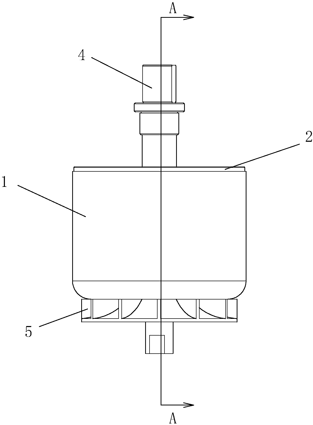
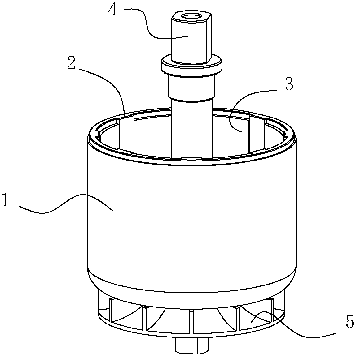
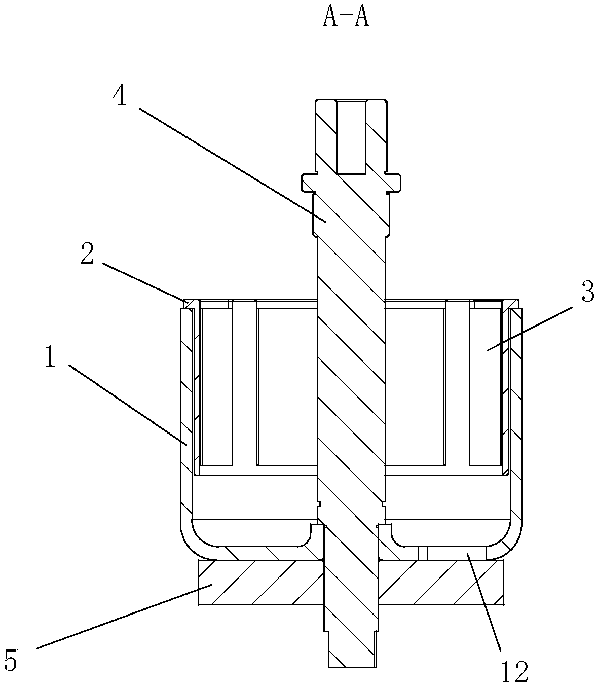
[0030] See Figure 1 to Figure 3 , The brushless motor outer rotor assembly with a simple structure of the present invention includes a motor housing 1 , a cage 2 , a permanent magnet 3 , a drive shaft 4 and fan blades 5 .

[0031] See figure 2 , image 3 , Figure 5 and Image 6 , The motor casing 1 is an integral piece made of iron or low carbon steel, and the motor casing 1 of this embodiment is made of 20 steel. The motor casing 1 is a casing with an upward opening, and the wall thickness of the motor casing 1 is 2 mm to 6 mm (3 mm in this embodiment). The center of the bottom of the motor housing 1 is provided with a shaft hole 11 that runs through it. The shaft hole 11 is formed by punching and stretching. The axial depth of the shaft hole 11 should be 4 mm to 8 mm (6 mm in this embodiment). The bottom of the motor casing 1 is provided with a set of cooling holes 12 running through it. The cooling holes 12 are arranged around the shaft hole 11 .

[0032] See Fi...


PUM


Abstract

The invention discloses a brushless motor outer rotor assembly with a simple structure which comprises a motor shell, a retainer, permanent magnets and a drive shaft. The motor shell is an integral piece of iron or low carbon steel. The opening of the motor shell is upwards, and has a wall thickness with 2 mm to 6 mm. The drive shaft is coaxially and fixedly arranged in the motor shell and extendsout of the motor shell upwards. The retainer is an integral injection molded piece. The retainer comprises a positioning portion and an upper limit portion. The positioning portion has a cylindricalshape as a whole, and has a wall thickness with 1 / 3 to 1 of the thickness of the permanent magnet. An outer diameter of the positioning portion corresponds to an inner diameter of the motor shell. Positioning grooves with the same number as the number of permanent magnets are arranged with the positioning portion at equal intervals in the circumferential direction of the positioning portion, and the shape thereof corresponds to the permanent magnets. The upper limiting portion is arranged on the upper outer circumference of the positioning portion. The retainer is adhesively fixed in the motorshell. The permanent magnets comprise an N permanent magnet and an S permanent magnet sequentially arranged in the positioning grooves of the retainer and adhesively fixed on the motor shell.

Description

technical field [0001] The invention relates to the field of motors, in particular to an outer rotor assembly of a brushless motor. Background technique [0002] The rotor part of an ordinary external rotor motor usually includes a casing, a permanent magnet and a magnetic coil. The permanent magnets are divided into N poles and S poles due to the magnetization direction, hereinafter referred to as N permanent magnets and S permanent magnets. The housing is usually aluminum die-casting, because the drive shaft needs to cooperate with the magnetic coil through the housing to meet the requirements of the outer rotor, so the magnetic coil must be fixed in the housing. The magnetic ring is usually a stamped piece of silicon steel sheet. Grooves for positioning permanent magnets are processed inside the magnetic ring. The permanent magnets are fixed in the grooves on the magnetic ring. N permanent magnets and S permanent magnets are alternately arranged at intervals. The magneti...

Claims


Application Information

Patent Timeline
Patent Type & Authority Applications(China)
IPC IPC(8): H02K5/04H02K1/27H02K1/30
Inventor 张小荣陈坚跃刘政
Owner CHANGZHOU CREATE ELECTRIC APPLIANCE
Why Eureka
Try Eureka