Clock synchronization method, system and optical transmission equipment
A clock synchronization and equipment technology, applied in the field of communication, can solve the problems of inability to achieve clock synchronization, large time synchronization jitter, etc.
- Summary
- Abstract
- Description
- Claims
- Application Information
AI Technical Summary
Problems solved by technology
Method used
Image
Examples
Embodiment 1
[0084] The realization block diagram of this embodiment is as attached Figure 5 shown.
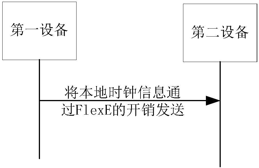
[0085]The device in the sending direction: first obtain the sending time stamp according to the local time and the sending position of the overhead corresponding to the time information packet header, and encapsulate the sending time stamp into the time information message. Afterwards, the time information message is inserted into the reserved field (ie reserved field) of the FlexE overhead frame in blocks, together with other information to generate an overhead frame, and then the overhead frame is inserted into the data stream of PHY0. It is also possible to insert the time information message into the overhead frames of other PHYs.
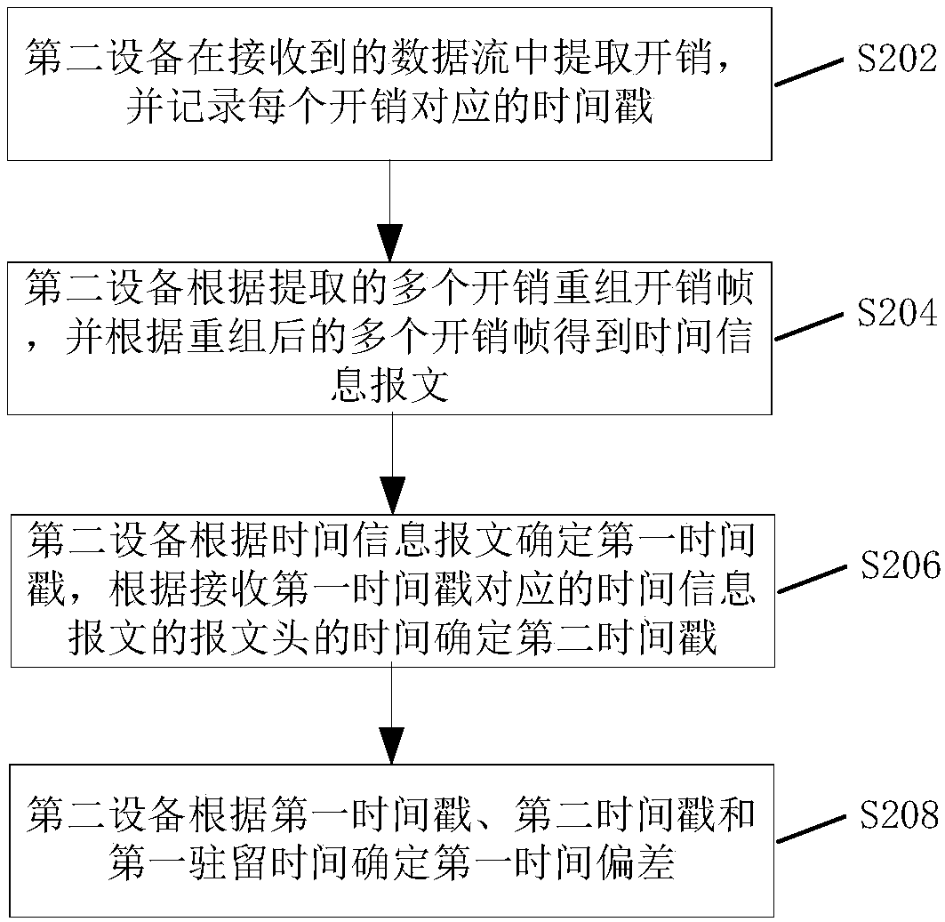
[0086] Device in the receiving direction: first extract the overhead from the data stream of PHY0, and record the timestamp of the overhead position, reassemble the overhead frame according to the extracted overhead, extract the time information message f...
Embodiment 2
[0093] This implementation mode introduces a scheme in which different processing units are respectively implemented in two components. Among them, component 1 implements functions such as insertion and extraction of overhead frames, reassembly of overhead frames, and recording of sending and receiving time stamps. Component 2 implements functions such as time information message generation, overhead frame generation, time stamp extraction, time synchronization and frequency synchronization. The internal messages of component 1 and component 2 are transmitted through the GE port, and the block diagrams of the sending direction and receiving direction are shown in the attached Figure 8 And attached Figure 9 shown.
[0094] The time information can be transmitted in the overhead reserved field of a line of FlexE. In this embodiment, the 0th line is selected, and the time information is added to the overhead reserved field of PHY0.
[0095] In the sending direction, componen...
PUM
 Abstract
Description
Claims
Application Information
 - R&D
- Intellectual Property
- Life Sciences
- Materials
- Tech Scout
- Unparalleled Data Quality
- Higher Quality Content
- 60% Fewer Hallucinations
Browse by: Latest US Patents, China's latest patents, Technical Efficacy Thesaurus, Application Domain, Technology Topic, Popular Technical Reports.
© 2025 PatSnap. All rights reserved.Legal|Privacy policy|Modern Slavery Act Transparency Statement|Sitemap|About US| Contact US: help@patsnap.com


