
Clock synchronization method, system and optical transmission equipment

A clock synchronization and equipment technology, applied in the field of communication, can solve the problems of inability to achieve clock synchronization, large time synchronization jitter, etc.

Active Publication Date: 2021-04-23
SHENZHEN ZHONGXING SOFTWARE CO LTD
View PDF7 Cites 0 Cited by
  • Summary
  • Abstract
  • Description
  • Claims
  • Application Information

AI Technical Summary

Problems solved by technology

[0003] The present invention provides a clock synchronization method, system and optical transmission equipment to solve the following problems in the prior art: when transmitting time information, due to the different fiber lengths of the lines corresponding to the FlexE interface, the link delay will continue The greater the difference in fiber length, the greater the jitter of time synchronization, and it is impossible to achieve accurate clock synchronization

Method used


Image

  • Clock synchronization method, system and optical transmission equipment
  • Clock synchronization method, system and optical transmission equipment
  • Clock synchronization method, system and optical transmission equipment

Examples


Embodiment 1

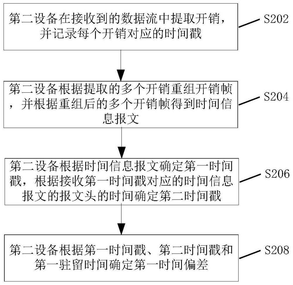
[0084] The implementation block diagram of this embodiment is as attached Figure 5 shown.

[0085]The device in the sending direction: first obtain the sending time stamp according to the local time and the sending position of the overhead corresponding to the time information packet header, and encapsulate the sending time stamp into the time information message. Afterwards, the time information message is inserted into the reserved field (ie reserved field) of the FlexE overhead frame in blocks, together with other information to generate an overhead frame, and then the overhead frame is inserted into the data stream of PHY0. It is also possible to insert the time information message into the overhead frames of other PHYs.

[0086] Device in the receiving direction: first extract the overhead from the data stream of PHY0, and record the timestamp of the overhead position, reassemble the overhead frame according to the extracted overhead, extract the time information messag...

Embodiment 2

[0093] This implementation mode introduces a scheme in which different processing units are respectively implemented in two components. Among them, component 1 implements functions such as insertion and extraction of overhead frames, reassembly of overhead frames, and recording of sending and receiving time stamps. Component 2 implements functions such as time information message generation, overhead frame generation, time stamp extraction, time synchronization and frequency synchronization. The internal messages of component 1 and component 2 are transmitted through the GE port, and the block diagrams of the sending direction and receiving direction are shown in the attached Figure 8 And attached Figure 9 shown.

[0094] The time information can be transmitted in the overhead reserved field of a line of FlexE. In this embodiment, the 0th line is selected, and the time information is added to the overhead reserved field of PHY0.

[0095] In the sending direction, componen...


PUM


Abstract

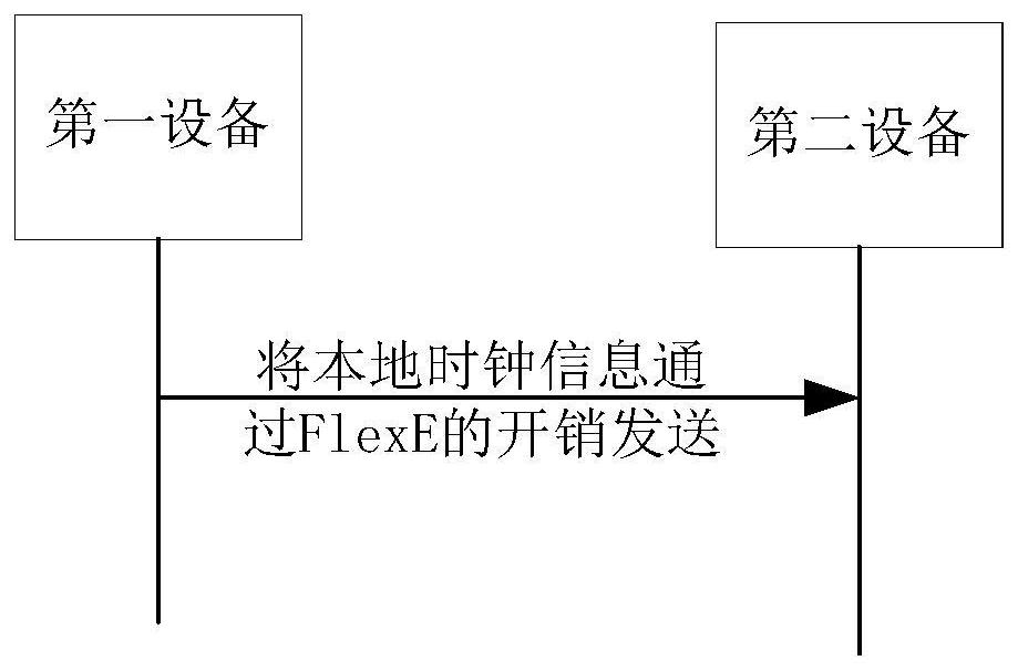
The present invention discloses a method and device for clock synchronization. The method includes: a first device sends local clock information to a second device through FlexE overhead, so that the second device performs clock synchronization according to the local clock information of the first device . In the present invention, the first device sends the local clock information to the second device through the overhead of FlexE, so that the second device performs clock synchronization according to the local clock information of the first device, and completes the transfer of the time information message by sending the overhead frame. The transfer process Not affected by different fiber lengths, clock synchronization can be accurately realized, which solves the following problems in the prior art: when transmitting time information, due to the different fiber lengths of the lines corresponding to the flexE interface, the link delay will continue The greater the difference in fiber length, the greater the jitter of time synchronization, making it impossible to achieve clock synchronization.

Description

technical field [0001] The invention relates to the communication field, in particular to a clock synchronization method, system and optical transmission equipment. Background technique [0002] Because of its flexibility, the FlexE interface is more and more widely used, for example, it is widely used in the fronthaul network. But at the same time, because of its flexibility, the time information generated by the client side cannot be fixedly transmitted on one line. If the fiber lengths of several lines of FlexE are different, the link delay will continue to change, and the time synchronization will also be affected. If there is jitter, the greater the difference in fiber length, the greater the jitter of time synchronization, and precise time synchronization cannot be achieved. Contents of the invention [0003] The present invention provides a clock synchronization method, system and optical transmission equipment to solve the following problems in the prior art: when...

Claims


Application Information

Patent Timeline
Patent Type & Authority Patents(China)
IPC IPC(8): H04J3/06H04J14/02
CPCH04J3/0661H04J14/0227
Inventor 李霞刘峰何力罗彬游俊
Owner SHENZHEN ZHONGXING SOFTWARE CO LTD
Learn More