
No-current monostable electromagnetic servo equipment and its application

A servo equipment, no current technology, applied in the direction of electromagnets, electromagnets, magnets, etc. with armatures, can solve the problems of reduced efficiency, reduced armature acceleration time, poor dynamic characteristics

Active Publication Date: 2021-03-30
ETO MAGNETIC GMBH
View PDF10 Cites 0 Cited by
  • Summary
  • Abstract
  • Description
  • Claims
  • Application Information

AI Technical Summary

Problems solved by technology

However, this is precisely not without problems technically, but can be disadvantageous, since it is precisely the permanent magnets on the armature side, in particular in the (generally) magnetically conductive housing of the servo unit (which is usually necessary for the servo functionality). Adhesion at the corresponding final position, ie, the adhesion effect first forms bistable there
It follows that, for example, a spring forming a restoring force or a counterforce reduces the efficiency of the entire arrangement, because it is during the (downward) movement from the stop position on the armature side that, in addition to the permanent force already acting there, In addition to the magnetic attraction, the corresponding force of the return spring must be overcome
In addition to the negative consequences for efficiency, this also leads to poor dynamic behavior, that is to say, the acceleration of the armature is reduced and the time required to extract the armature unit with the tappet section is correspondingly increased, which is precisely the case in motor vehicles. Aspects that should generally be avoided
[0008] For this reason, for example, in the above-mentioned widespread prior art according to the document DE 201 14 466 U1, a disadvantage arises that there are usually provided for loosening the armature unit from the first servo position mainly in order to improve the dynamic behavior. Detached pressure springs, so that (theoretically conceivable) return springs are counterproductive or problematic at first here

Method used


Image

  • No-current monostable electromagnetic servo equipment and its application
  • No-current monostable electromagnetic servo equipment and its application
  • No-current monostable electromagnetic servo equipment and its application

Examples


Embodiment Construction

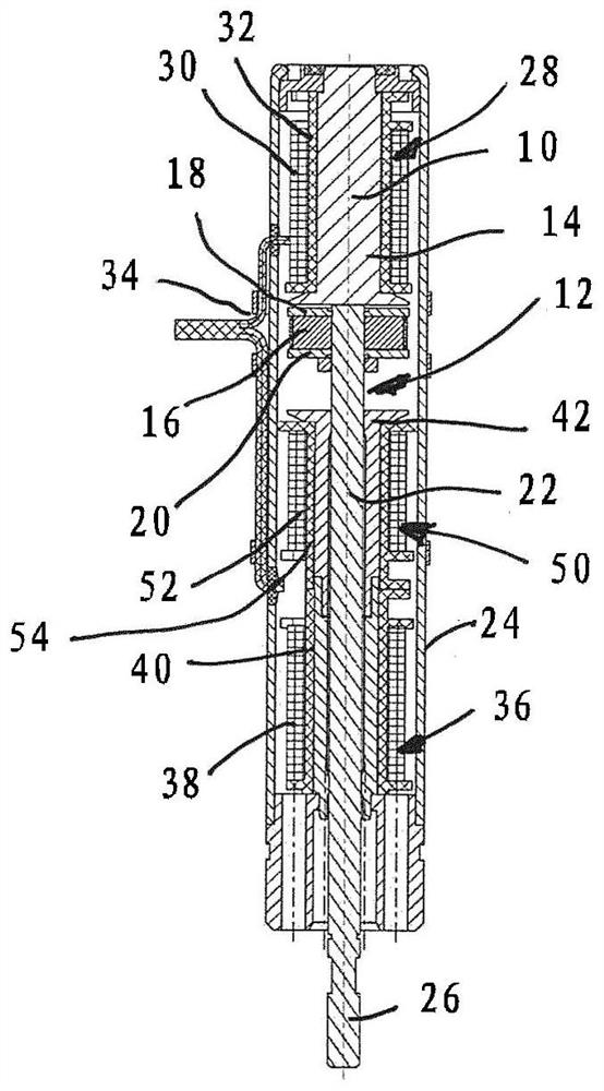
[0029] figure 1 The longitudinal section of the first embodiment of the present invention shows an armature unit 12 movable along a longitudinal axis 10, said armature unit having a permanent magnet piece 16 on a first end pointing towards a first core 14, said permanent The magnetic sheet is limited by the magnetic conductive sheets 18 and 20 at both ends in the axial direction. A longitudinally extending tappet section 22 of the armature unit is attached to the permanent magnet plate, said tappet section extending in the axial direction in the center of the surrounding cylindrical housing 24 to (at figure 1 (shown on the underside) open housing end, from which a toothing section 26 designed to interact with a servo fitting provided here in a motorcycle transmission is formed.

[0030] In a manner known, for example, from the state of the art according to DE 201 14 466 U1, the static first core 14 is surrounded by a first coil unit 28 having a coil (for example embodied as a...


PUM


Abstract

The invention relates to a current-free, monostable electromagnetic actuating device having an armature unit with a permanent magnet, which has a snap-in or engagement section for cooperating with a tappet section, the armature unit being able to move from The currentlessly stable first servo position is shifted to the second servo position against the restoring force of the energy storage device, the coil device has a first coil unit which can be connected to the circuit in order to exert the armature unit from The loose force in the first servo position, the coil device also has a second coil unit that can be connected into the circuit so that the second coil unit exerts a force on the armature unit that accelerates the armature unit when shifting, the coil device There is a reset coil device, which can be connected to the circuit, so that the reset coil device strengthens the reset force of the energy storage device when the armature unit returns from the second servo position to the first servo position. The invention also relates to the use of a current-free monostable electromagnetic servo of the aforementioned type.

Description

technical field [0001] The invention relates to a currentless monostable electromagnetic servo device. Furthermore, the invention relates to the use of this type of currentless monostable electromagnetic actuating device. Background technique [0002] Electromagnetic servo devices are considered to be widely known in the prior art. For example, in the document DE 20114 466 U1 of the applicant, a bistable electromagnetic actuating device is disclosed as a servo device, which has an armature unit equipped with a permanent magnet and a tappet unit extending lengthwise in the direction of motion, The tappet unit is mounted on the armature unit. The permanent-magnet armature unit is driven by means of static electromagnetic drive means in the form of a static core unit, to which a suitably energizable coil unit is assigned. In particular to improve the withdrawal of the armature unit, that is to say the movement of the armature unit away from the current-free, stable first (in...

Claims


Application Information

Patent Timeline
Patent Type & Authority Patents(China)
IPC IPC(8): H01F7/122H01F7/16
CPCH01F7/122H01F2007/1692H01F7/1615H01F7/081H01F7/1646H01F2007/086H01F2007/1669
Inventor P.范高尔P.温康
Owner ETO MAGNETIC GMBH
Learn More