
Motor and method of manufacturing the motor

A manufacturing method and motor technology, applied in the manufacture of motor generators, connection with control/drive circuits, electromechanical devices, etc., can solve the problems of increased motor assembly workload, difficult terminal module installation, etc., and achieve the effect of reducing assembly workload

Active Publication Date: 2020-11-13
NIPPON DENSAN CORP
View PDF1 Cites 0 Cited by
  • Summary
  • Abstract
  • Description
  • Claims
  • Application Information

AI Technical Summary

Problems solved by technology

[0005] However, in the motor disclosed in Japanese Patent Application Laid-Open No. 2015-109742, when the terminal module is mounted on the housing, the terminal member and the leading end of the lead wire may interfere in the axial direction, making it difficult to mount the terminal module to the specified position. s position
Therefore, there is a problem that the assembly work load of the motor increases

Method used


Image

  • Motor and method of manufacturing the motor
  • Motor and method of manufacturing the motor
  • Motor and method of manufacturing the motor

Examples


Embodiment Construction

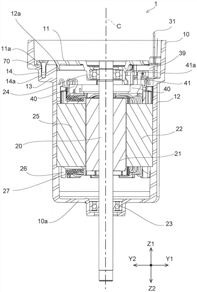
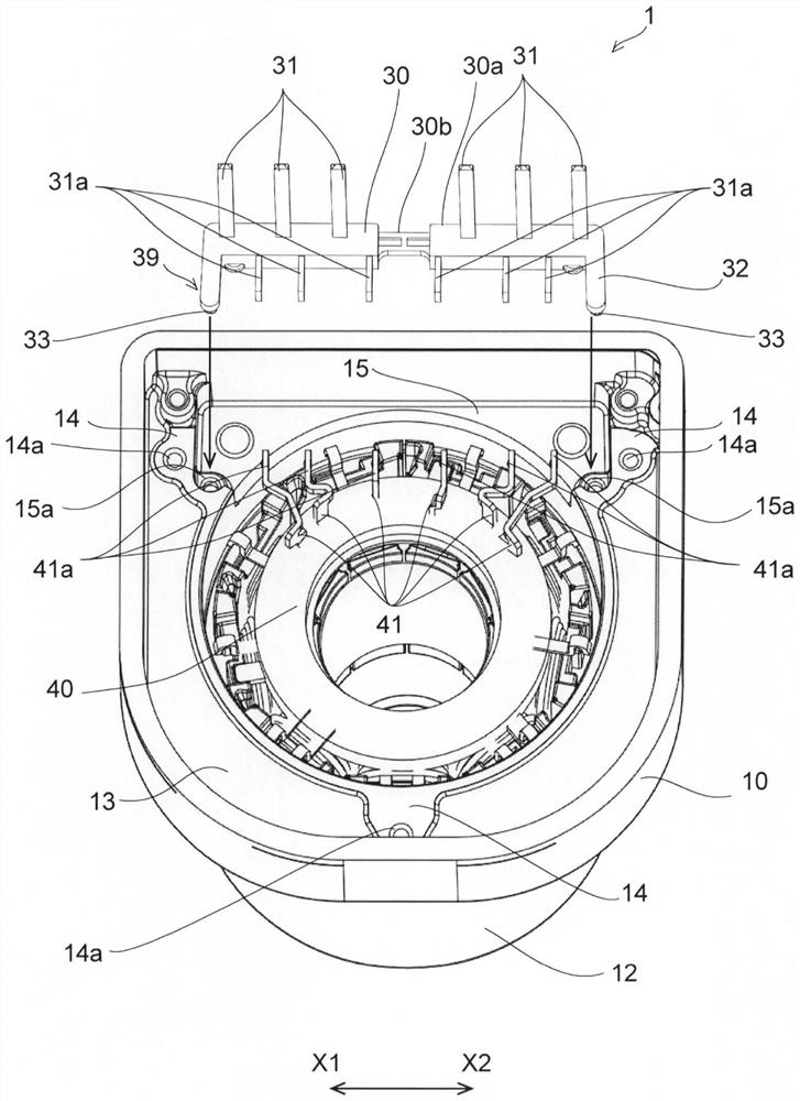
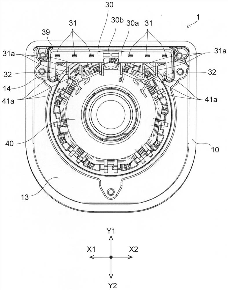
[0019] Below, while referring to the attached Figure 1 Exemplary embodiments of the present invention will be described in detail. Additionally, the figure 2 The direction in which the central axis C of the motor 1 extends is simply referred to as "axial direction", and the radial and circumferential directions centered on the central axis C of the motor 1 are simply referred to as "radial" and "circumferential". In addition, in Figure 4 In the plan view of the motor 1 viewed from the axial direction, the direction in which the front end of the bus bar connecting portion 41a extends is referred to as the “front-rear direction”, and the direction in which the plurality of bus bar connecting portions 41a are aligned is referred to as the “left-right direction”. The "axial direction", the "front-rear direction", and the "left-right direction" are perpendicular to each other. exist Figure 4 In the "left-right direction", when the terminal pin 31 is viewed from the central ...


PUM


Abstract

The motor has: a rotor having a rotating shaft; a stator having a plurality of coils facing the rotor; a cylindrical casing having an opening at one end in the axial direction and holding the stator; a plurality of bus bars , which have a bus bar connection portion extending in the axial direction at one end, and the other end is connected to each coil; a plurality of terminal pins, which have a terminal connection portion at one end, and the terminal connection portion is connected to the bus bar connection portion at Opposite and connected to the first direction perpendicular to the axial direction; and a terminal bracket, which holds a plurality of terminal pins and is installed in the opening, the housing has a through insertion hole opened toward one end side of the axial direction, and the terminal bracket has The protruding part inserted into the insertion hole, one of the protruding part and the through insertion hole has: a fitting part, which fits with the other; and a guide part, which is located at the insertion end side of the fitting part, in the guide The side surface on the side in the first direction inclines in a direction opposite to the first direction as it moves away from the opening end of the insertion hole.

Description

technical field [0001] The present invention relates to a motor and a method of manufacturing the motor. Background technique [0002] Conventionally, there is a motor in which a stator and a rotor having a rotating shaft are accommodated in a cylindrical casing having an opening at one end in the axial direction (for example, disclosed in JP-A-2015-109742). The rotor contains magnets surrounding an axially extending shaft. The stator has a plurality of coils, and is arranged on the radially outer side of the rotor and faces the rotor. [0003] One end of each lead wire extending from each coil is formed to extend in the axial direction. Each lead wire is connected to a plurality of terminal members provided in the terminal block, and each terminal member is in contact with a plurality of conductors (terminal pins) held by the terminal block. The conductor is extended to the outside of the case to be connected to an external power source or the like. [0004] Here, each ...

Claims


Application Information

Patent Timeline
Patent Type & Authority Patents(China)
IPC IPC(8): H02K5/22
CPCH02K5/22H02K2203/09H02K3/522H02K5/225H02K3/50H02K11/33H02K5/1732H02K15/0062
Inventor 朝日优芳贺英博村上俊辅前田昌良
Owner NIPPON DENSAN CORP
Learn More