Carpet box with capillary water absorption function

A capillary water absorption and carpet technology, which is applied in the field of carpets, can solve the problems of inconvenience for pedestrians and cleaning personnel, poor water absorption capacity, soiling of shoe uppers and ground, etc., and achieve the effect of improving water absorption effect and water absorption capacity

Active Publication Date: 2018-11-27
嘉兴瑞知环保科技有限公司
View PDF13 Cites 14 Cited by
  • Summary
  • Abstract
  • Description
  • Claims
  • Application Information

AI Technical Summary

Problems solved by technology

[0003] On rainy days, in shopping malls, hotels and other places, there is a large flow of people. Due to the limitation of carpet materials, after a period of time, the carpet will often reach the state of water absorption satu

Method used


Image

  • Carpet box with capillary water absorption function
  • Carpet box with capillary water absorption function
  • Carpet box with capillary water absorption function

Examples


Embodiment 1

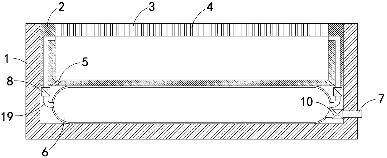
[0018] like figure 1 As shown, a capillary water-absorbing carpet box includes a box body 1 with an opening at the upper end, and a movable box 2 that can move in the vertical direction is provided in the box body 1. Regarding the limitation of the movable box 2, the movable box can be moved by sliding Block chute and other conventional means to achieve, do not go into details here, the upper end of the movable box 2 is fixedly connected with a pedal 3, the pedal 3 is evenly provided with a plurality of capillary holes 4 that penetrate up and down, and the bottom of the movable box 2 is provided with a plurality of Drain holes 5 for drainage. It should be noted that a drain valve (not shown) for drainage is provided on the side wall of the box body 1. When there is too much water in the box body 1, the accumulated water can be discharged in time. The first air bag 6 with elasticity is fixedly connected between the lower end of the movable box 2 and the inner bottom surface of ...

Embodiment 2

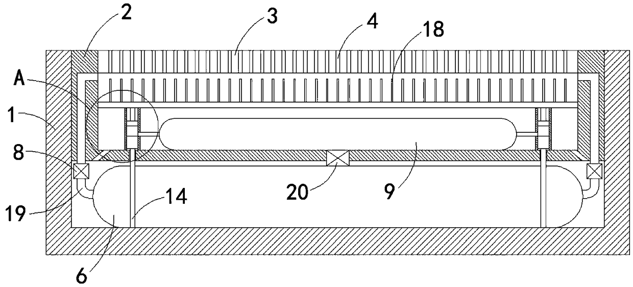
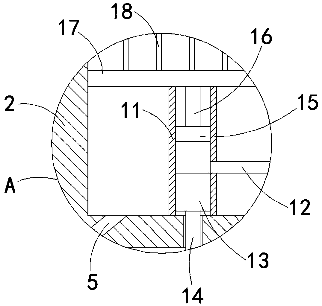
[0021] like Figure 2-3 As shown, the difference between this embodiment and Embodiment 1 is that the exhaust mechanism includes a second air bag 9 fixedly connected to the inner bottom surface of the movable box 2, and the second air bag 9 is connected to the first air bag 6 through a third one-way air bag. The valve 20 is connected, and the third one-way valve 20 allows the gas to enter the second air bag 9 from the first air bag 6 in one direction. Two cylinders 11 are arranged on both sides of the second air bag 9, and the lower end of the cylinder 11 is in contact with the movable The inner bottom surface of the box 2 is fixedly connected, and the cylinder 11 and the second air bag 9 are connected through the second exhaust pipe 12. The piston block 13 is connected to the cylinder 11 in a sliding seal, and the lower limit position of the piston block 13 is at the second position. The lower side of the output end of the exhaust pipe 12, the lower end of the piston block 13...


PUM


Abstract

The invention belongs to the field of carpets and particularly relates to a carpet box with a capillary water absorption function. The carpet box includes a box body with an opening in the upper end,a movable case capable moving in the vertical direction is arranged in the box body, a pedal is fixedly connected to the upper end of the movable case, multiple capillary holes uniformly run through the upper and lower portions of the pedal, multiple drain holes used for drainage are formed in the bottom of the movable case, and an elastic first airbag is fixedly connected between the lower end ofthe movable case and the inner bottom surface of the box body and communicated with the movable case through multiple retractable hoses; a first check valve is fixedly connected to each retractable hose, and a venting mechanism is arranged on the side wall of the first airbag. Water on people's shoe soles is absorbed by means of a capillary phenomenon and then discharged, correspondingly the capillary holes can always maintain a great water absorption capability, and the water absorption effect of a carpet is effectively improved. Moreover, through arrangement of a second airbag, the capillary holes can be cleaned in time, and blockage is avoided.

Description

technical field [0001] The invention belongs to the field of carpets, in particular to a capillary water-absorbing carpet box. Background technique [0002] Carpets are still limited to hotels, hotels, office buildings, offices, restaurants and other places in China, while in the United States and western developed countries, commercial carpets have been used in airport terminals, wharf boat halls, and waiting stations in addition to the above-mentioned places. Halls, supermarkets, hospitals, schools, nursing homes, nurseries, theaters and other places are widely used, and with economic development and social progress, the scope of use of commercial carpets will gradually increase, and the coverage will be wider. [0003] On rainy days, in shopping malls, hotels and other places, there is a large flow of people. Due to the limitation of carpet materials, after a period of time, the carpet will often reach the state of water absorption saturation. On the contrary, when peopl...

Claims


Application Information

Patent Timeline
IPC IPC(8): A47L23/24
CPCA47L23/24
Inventor 陈龙
Owner 嘉兴瑞知环保科技有限公司
Why Eureka
Try Eureka